kman wrote: ↑August 5th, 2023, 3:20 am July 5, 2023. YouTube is dangerous.
Watching a bunch of upgrade videos on RSquad911's YouTube channel really got me SUPER hooked on the potential of all these mods, and so many more that I wanted to emulate. Note: I have decided I kinda don't care about *exactly* matching the AfterLife Phoebe pack anymore, although I do still want to try matching it in spirit.
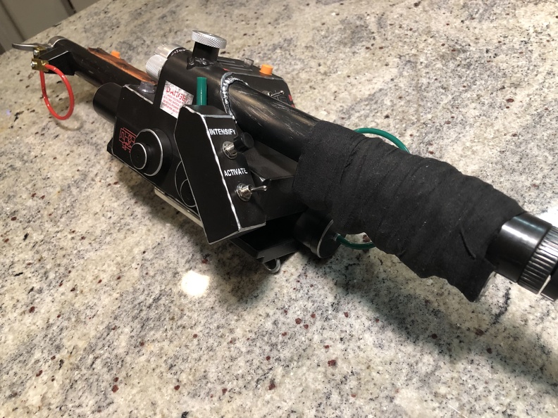
I picked up some black hockey tape from Amazon, and wrapped right over that awful plastic tape on the wand handle. HUGE improvement.
Aaaand I'm now dissatisfied with the stock hose loom... so stiff and annoying! Charlesworth Dynamics has a replacement loom that's SO much nicer. Flexible, coils nicely, etc. And while I had, earlier on, considered simply painting the hard rubber "oxygen hose" part of the stock hose (as a friend did), it's lack of flexibility was getting more and more annoying to me, especially looking at packs with the oxygen hose. I ordered some black oxygen hose from AliExpress. It would be slow to arrive, and black instead of olive, but... it's the spirit of the mod, right? Not to mention the practicality, getting away from that awful stiff "rubber" (aka flexible plastic?) part. Instead of hard to find and expensive Neutrik connectors, I went with CNLINKO disconnects from Amazon. Looking forward to getting all this installed.
July 23, 2023:
I made the mistake of getting back on Facebook after a long hiatus, and stumbled across the HasLab pack modders group. Chris Hunt at DragonWorkshop seduced me with photos of his incredible drop in Cyclotron lid interior kit.
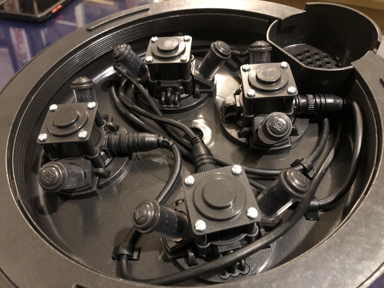
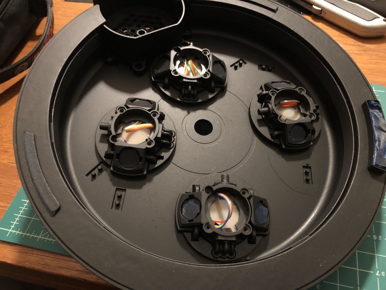
That took me from this stock setup:
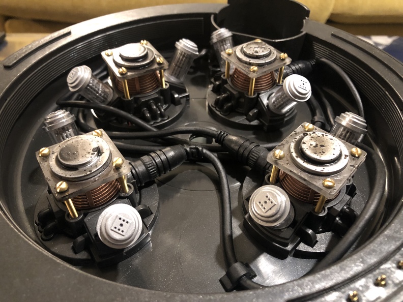
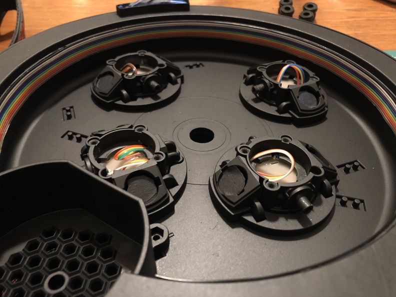
... to this:
... just by unscrewing the stock stuff and screwing in his kit, instead. Which looks amazing.
Except now the weathering is totally uneven and weird looking. Some serious weathering is in order.
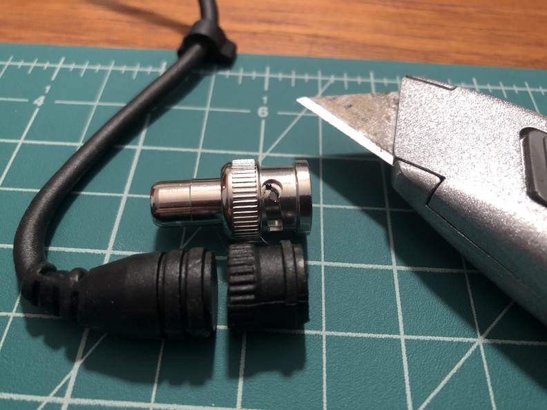
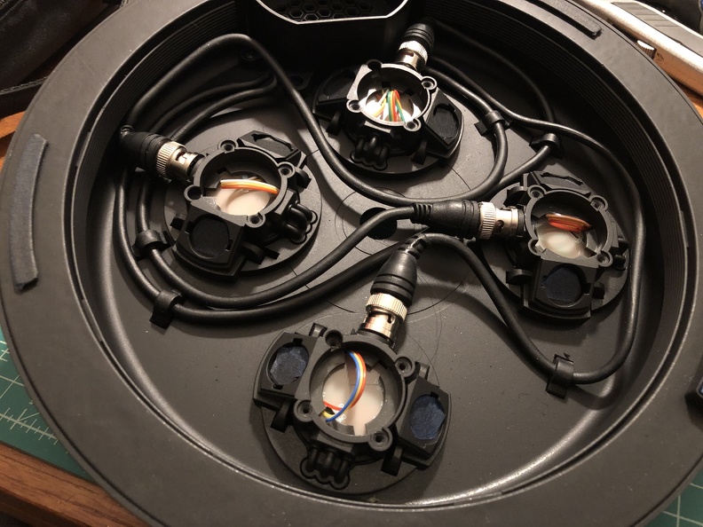
First, though, I could no longer stand the rubber BNC cables, so, copying a mod someone else did in the Facebook group, I picked up some cheap RCA-to-BNC connectors on eBay, chopped off the offending rubber ends, and drilled into the stock "stubs".
While I was in there, I started the repaint, starting with a simple coat of flat black Rustoleum rattle can (standard 2X stuff):
Here's the end result cable, on that newly-painted surface:
They're just friction fit for now, but I'll probably either hot glue or maybe even E6000 the two of those that free float a little more, as they've worked their way off once or twice.
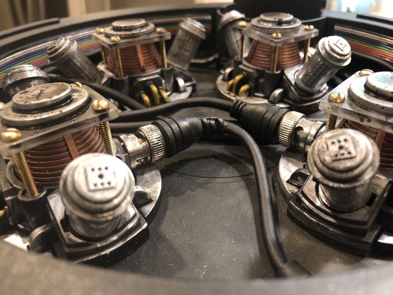
But first I added the rainbow ribbon cable to the lid interior (amazon buy):
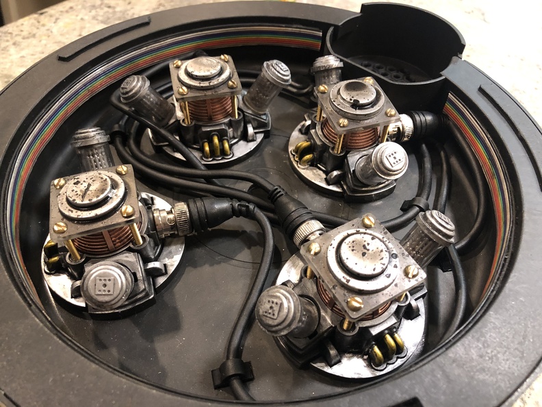
Next up, while everything was still out (or easily removed), I used silver rub n buff to "metallize" the base modules, and my good ol' gold Sharpie for the "copper pipes" (wires?), as the reference photos showed for the interiors. Then I weathered down the plastic a bit with a simple black acrylic wash, along with some burnt umber and raw sienna, to make it nice and grimy inside, and put it all back together. YES.
Aaaaand now I'm hooked on interior upgrades.
To be continued in the next post...
just my (un)professional opinion, but i think a great idea for the inside of the cyclotron bay lid/pan would be to get male COAX to BNC, that way you can cut the nubs off and screw the COAX end directly into the plastic. It'd look great and it adds another awesome thing you can fiddle with. I personally think the gear is more fun if it has parts that can be pulled off/unplugged/removed without tools, like actual unplug-able BNC connectors. But that's just me, it seems like a waste to have the connectors permanently attached.
The_Y33TER wrote: ↑October 2nd, 2023, 7:54 pmPlease, god, buy a Harsin3D grip. not only because it's beautiful but also because it supports Randall (luckily a buddy of mine from before he started selling the grips ) Also, the grip I recommend is the rear rounded, all it takes is cutting off the awful green tape and it's just a snap on 3d printed part. If you want, you can paint/sand it, but I'm running it unpainted, it's still comfy.
I'm not a fan of the appearance of 3D printed fake wood... and honestly real wood is easier to work with, doesn't require fancy paint techniques (that can scrape off!) to approximate the look and sheen of wood, weathers better, and lasts longer, and looks (and feels!) like... wood. The need to snap over the existing stuff makes you end up with an oversized grip, too. And after all that, the price ends up pretty darned similar, too.
I'm looking forward to having a real wood grip on this. Probably going to be after Halloween, though, too much work on family costumes to spend time on my own stuff right now.
For people less comfortable working with wood, though, the Harsin grips are a great solution.
The_Y33TER wrote: ↑October 5th, 2023, 9:12 amjust my (un)professional opinion, but i think a great idea for the inside of the cyclotron bay lid/pan would be to get male COAX to BNC, that way you can cut the nubs off and screw the COAX end directly into the plastic. It'd look great and it adds another awesome thing you can fiddle with. I personally think the gear is more fun if it has parts that can be pulled off/unplugged/removed without tools, like actual unplug-able BNC connectors. But that's just me, it seems like a waste to have the connectors permanently attached.
I've considered it. Not sure how necessary it is, since I don't really think I'm going to be messing around with unplugging and replugging cables inside the lid. But I might add that, someday. Perhaps if I ever get to the point where I install lighting inside the lid, I'll add that to the to-do list.
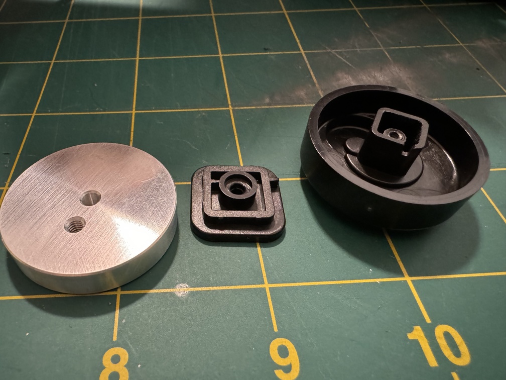
Well, I *finally* got my ion arm cap mounted, so that's a little more progress, I suppose, and makes it feel a LOT closer to the finish line. (Despite a few fairly big projects remaining)
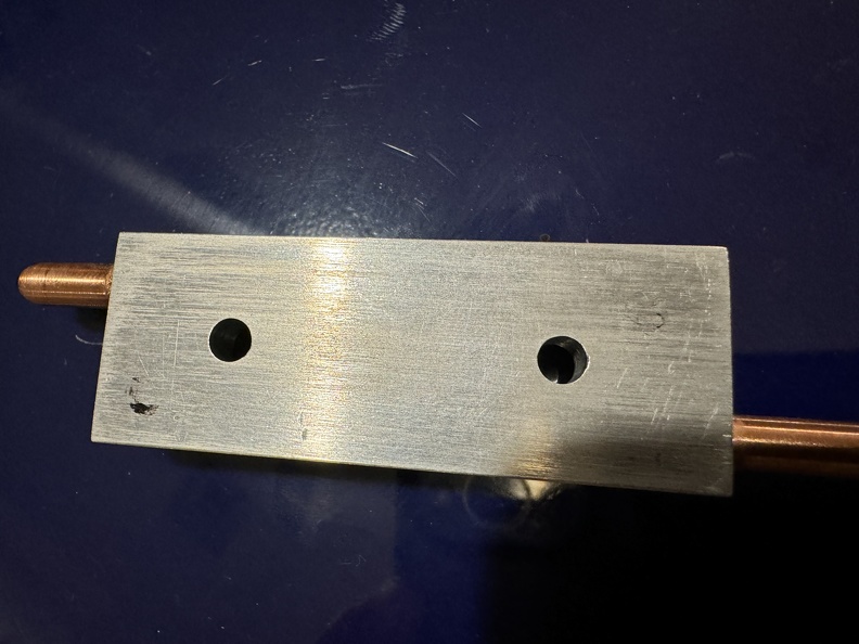
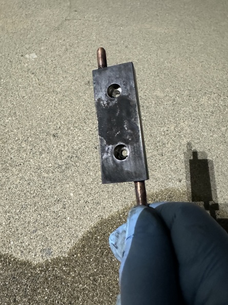
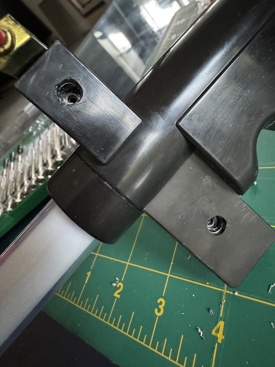
I have the Ben of Kent one, as mentioned earlier. The key was I wanted to maintain the ability to put back the original HasLabs cap, if I wanted. Normally, people cut off the nubs that hold the HasLab cap in place. So I decided I would mill holes into the back of the BoK cap, so I don't have to cut those nubs off. (Forgot to photograph the bare end, but I'm sure people can track down those photo if needed.)
I took off the HasLab cap, and used a paint pen to put a little black on the ends of the stock nubs sticking out the bare arm end. I carefully put the BoK cap against the nubs, right where I wanted to mount it, to get a little paint on the cap and mark the location I needed to mill.
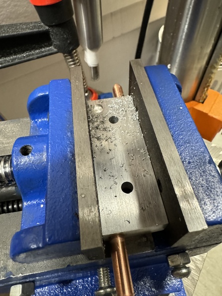
I have a little X/Y vice that goes on my drill press platform, and put a milling bit in, and started the process:
Now it slips right over those nubs without harming them at all (I suppose they help keep it aligned a little, too!). No photo of my just holding in place, sorry.
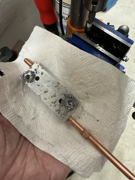
Next up came the Aluminum Black... I decided to go hardcore instead of just painting it.
Getting there...
Quick placement check, and then it's just a matter of drilling holes right through it for the screws.
And, done!
I still need to do a little actual weathering (read: scratching off some of the black to expose more metal), but I'm quite happy with this upgrade.
The differences between this and the original are small, but definitely there. And of course I can unscrew this and pop the original back on anytime I want.
The_Y33TER wrote: ↑October 2nd, 2023, 7:54 pmPlease, god, buy a Harsin3D grip. not only because it's beautiful but also because it supports Randall (luckily a buddy of mine from before he started selling the grips ) Also, the grip I recommend is the rear rounded, all it takes is cutting off the awful green tape and it's just a snap on 3d printed part. If you want, you can paint/sand it, but I'm running it unpainted, it's still comfy.
I'm not a fan of the appearance of 3D printed fake wood... and honestly real wood is easier to work with, doesn't require fancy paint techniques (that can scrape off!) to approximate the look and sheen of wood, weathers better, and lasts longer, and looks (and feels!) like... wood. The need to snap over the existing stuff makes you end up with an oversized grip, too. And after all that, the price ends up pretty darned similar, too.
I'm looking forward to having a real wood grip on this. Probably going to be after Halloween, though, too much work on family costumes to spend time on my own stuff right now.
For people less comfortable working with wood, though, the Harsin grips are a great solution.
Personally, I meant the rear grip. Nothing to do with wood at all!
The_Y33TER wrote: ↑November 3rd, 2023, 7:50 am Personally, I meant the rear grip. Nothing to do with wood at all!
Oh! Sorry, I know Harsin sells faux wood forestocks that snap over the stock HasLab ones. Thought that's what you meant.
I suppose I could do a replacement of the back handle section grip to get rid of the plastic tape entirely, but considering it's fully covered by hockey tape that works just fine, it's not going to be much of a priority.
Fair to add that to the long term list, though, once I start running out of mods LOL
Yep. Just a bit more... Comfy, in my opinion.
Last edited by Kingpin on November 6th, 2023, 2:37 pm, edited 1 time in total.Reason: Fixed quote code
Halloween was a busy time for this 'buster. And I have other tools in the fire I need to tend to. But baby steps are still happening.
I *started* the very beginnings of working on the wood shotgun stock for my wand. Cut out the wood crossbeam inside, and measured it to hack off the ends to shorten it. That'll come next, and then the sanding. We'll get there. Pics when there's more to see.
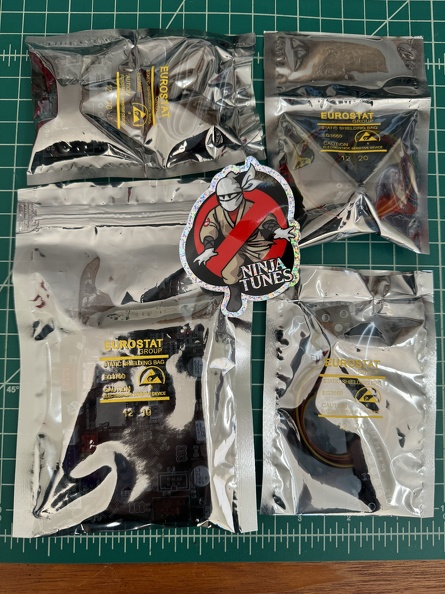
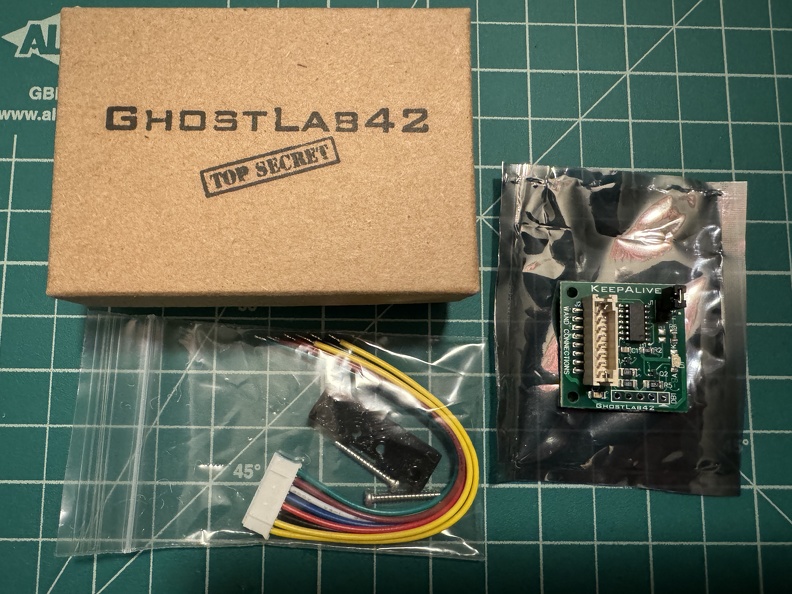
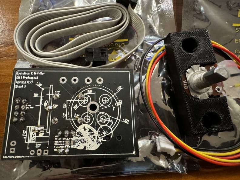
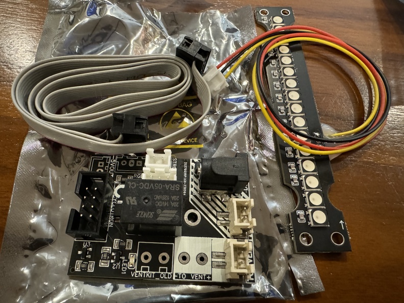
My NinjaTunes upgrade has arrived, and will be significantly upgrading the interior pack electronics soon.
And I'm getting Spongeface's wand keep-alive, too.
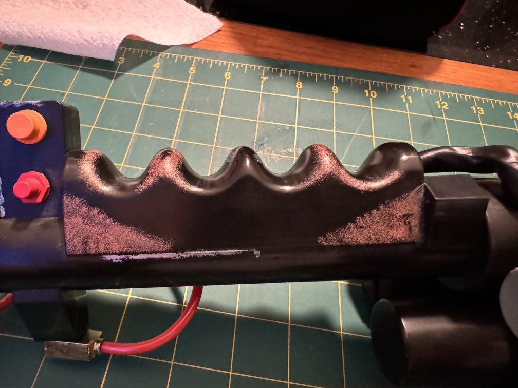
Once that mod comes in... I'm going to have to crack open the Spengler wand, finally. I've been putting it off a long time, but the time is rapidly approaching. While I'm in there, I want to round the edges of the stock heat sink, *might* add a metal upgrade or two... and probably a real Clippard. I probably will NOT do the vent cutout. I actually like the diffuser panel and think it looks good, in addition to serving the very valid purpose of keeping stuff from falling into the wand interior. Oh, and I very much need to repair the front wires... sadly, my Gen1 Spengler wand suffers the "inadequate wire protection" defect, and the tube LEDs are no longer firing.
Oh, and last but not least, I picked up one of TobyCJ's V hook replacements, so that final bit of exterior pack inaccurateness will be going away soon. I had really wanted to make this myself, but I ultimately caved in the interests of time, and bought Toby's, which is really nicely done.
After that... I think the only major things on my to-do list are real wire replacements around the Clippard (the "Phoebe wire shroud") and of course attaching the Redman motherboard, once it comes in. Maybe the side cutout mod... I'm on the fence on that one. And maybe cleaning up the interior of my snack compartment. I don't love the look of my button panel, at the moment, functional or not. I might want to move some switches to be accessible on the exterior, too, especially once the NT board is installed.
I added up what I've spent on this pack to date, the other day. Boy, THAT was a mistake LOL. #IgnoranceIsBliss
I've been super hesitant to go into my wand, but that's coming soon, as I run out of things to do on the pack. (Although there's still plenty, but some are awaiting parts, like the Redman motherboard which probably won't come until January, maybe.)
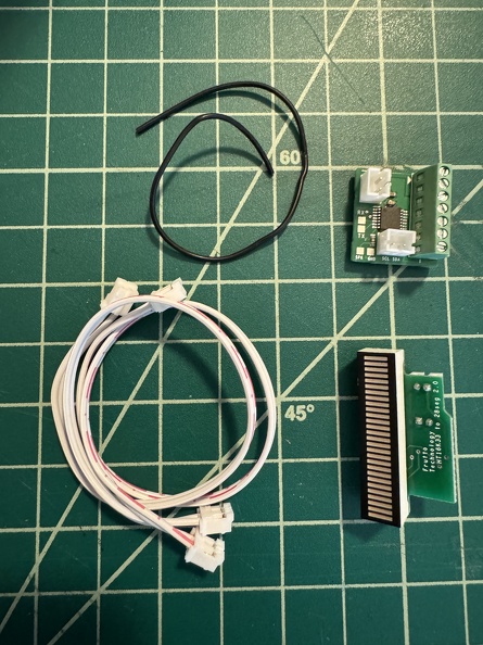
I bought the Frutto Tech 28 element bar graph upgrade for my want, and Spongeface's Spengler Wand Keep Alive board, so I'll be going in there soonish.
I wanted to join some of my peeps in the LA Ghostbusters group at Los Angeles Comic Con last weekend, so I decided it was time to bust open the pack again (hopefully the last time before the motherboard, but we'll see?) and install the NinjaTunes board, as well as install Toby's improved V-hook... man, the stock HasLab hook is fiddly.
Installing the V-Hook was stupid easy, once the pack was opened... the stock one is simply held on with nuts and bolts, so unscrewing them, sticking the new one into the same holes, and tightening the nuts on the new screws is all that was needed. Hardest part was getting my fingers into there to thread the nuts on.
I dirtied it up a little with some acrylic paint, but didn't do a full black paint and weathering ala Frozen Empire. I think I like the metal look better. Big improvement, though... not just the appearance, but the wand locks on a LOT more securely now. Still annoying to get it on, but that's the nature of the beast... this one is as easy as it's going to get, unless I switch to magnets.
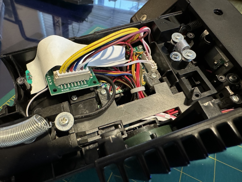
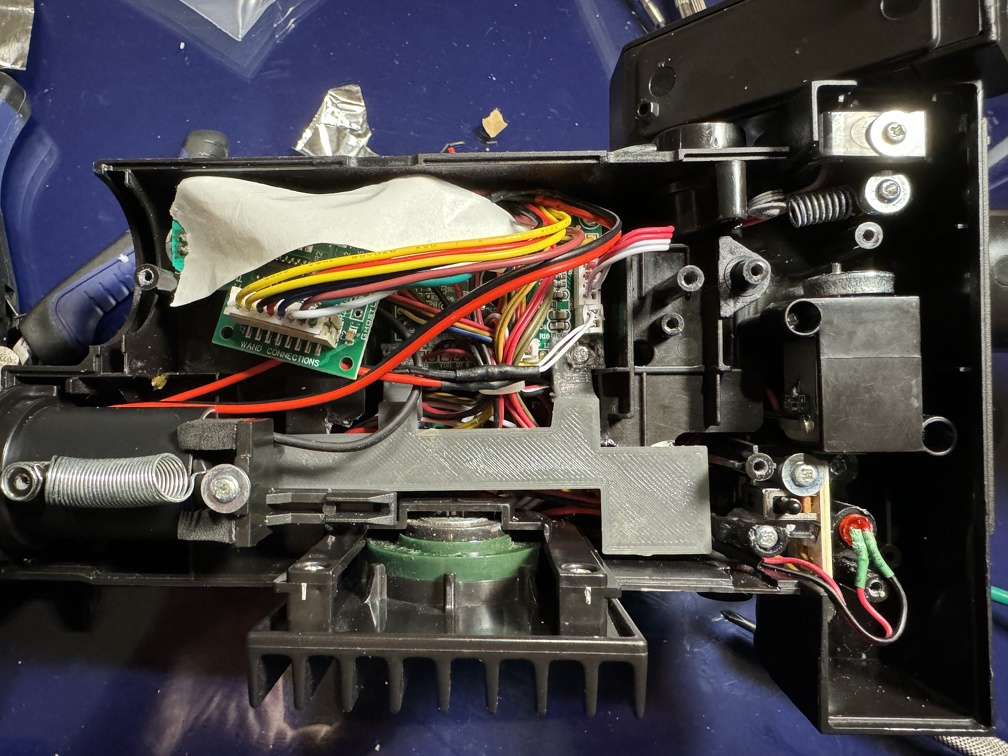
Last up was the NinjaTunes upgrade... pretty easy stuff, but involved a fair amount to get it all in, still.
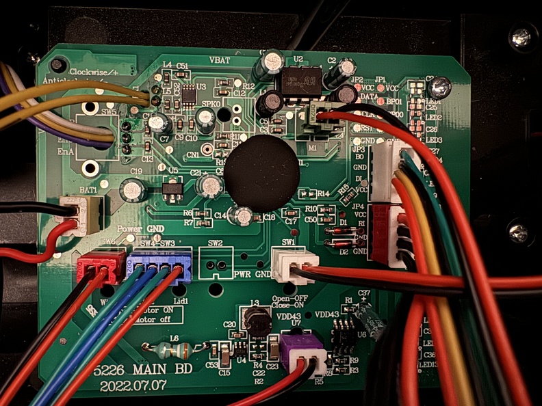
Removing the stock HasLab board simply involves unplugging the connectors from the sockets and unscrewing the two screws.
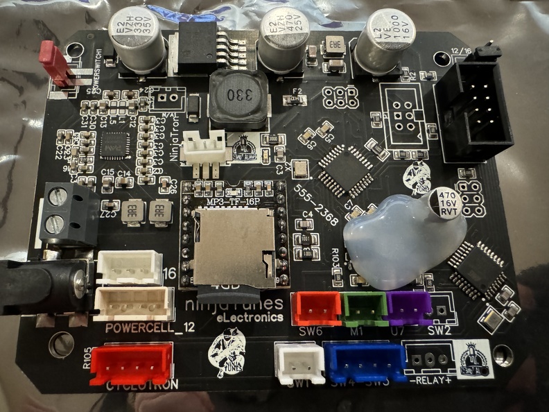
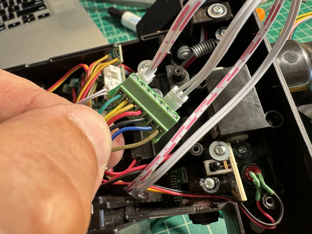
The NinjaTunes board goes into the same mounting spot, super easy, and then replug the same connectors into their color-coded sockets:
The speaker needed to be unscrewed and moved out of the way, so the volume knob could be replaced with the NT one (I'm a little surprised they couldn't make use of the stock knob, but I assume there's some electrical reason why that didn't work out, and the swap is just two screws, so super simple)
I had conveniently converted my speaker connection to a JST connector, but the NT board has screw terminals for bare wire, so I had to cut off my connector... oh well. I plan to upgrade the speaker to a 3" version (from the 2.5" Dayton I have now), once I get around to 3D printing the new mount, so that would have needed changing soon, anyway.
A little more arduous was disassembling half the pack to get to the bar graph LED on the pack, since HasLab really made that unreasonably complicated. But still, it's just a matter of more screws to disassemble stuff, and back. The old one comes out, and the new one goes in. Somewhat annoyingly, the blue acrylic upgrade lens I bought seems to not fit with the NT bargraph... I guess it's a bit thicker. So that had to come out. The LEDs are a nice blue without it, though, so there's that, I suppose... maybe it's not actually needed anymore.
Since I have Pierre Tran's cake LED upgrade kit installed, those wires piggyback the main board's wires. But the NinjaTunes kit, on the other hand, has a small extra board dedicated to managing this (plus relays for a future smoke kit), but the connector is different. So until I wire in a new connector, mine is staying running off the main board for now, as it was originally. The wiring will be cleaner once I can redirect them to the sub-board. The lights seem to work fine without it, so I guess no urgency on that.
Naturally I forgot to take a pic with everything in place, not that there's any particular magic to all that. I need to shoot some beauty shots of the full pack at some point soon, but I've sort of been waiting until I get the Phoebe wire surround (around the Clippard) done... maybe I'll do something sooner, though.
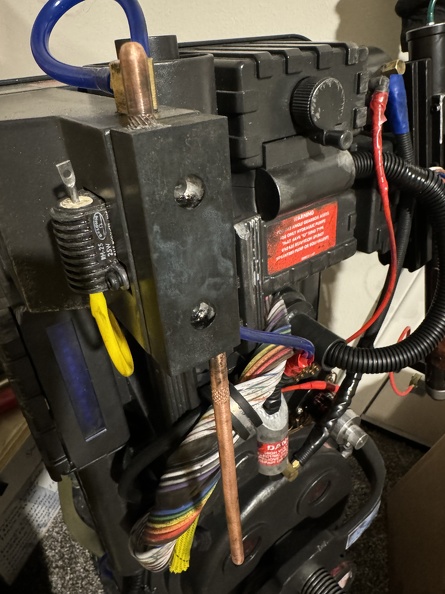
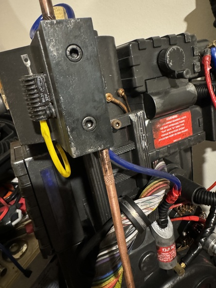
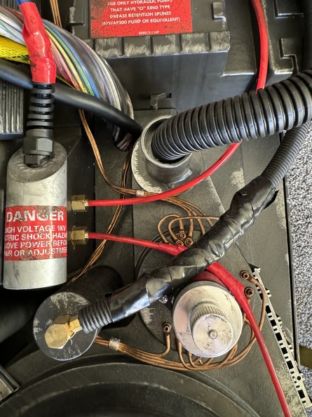
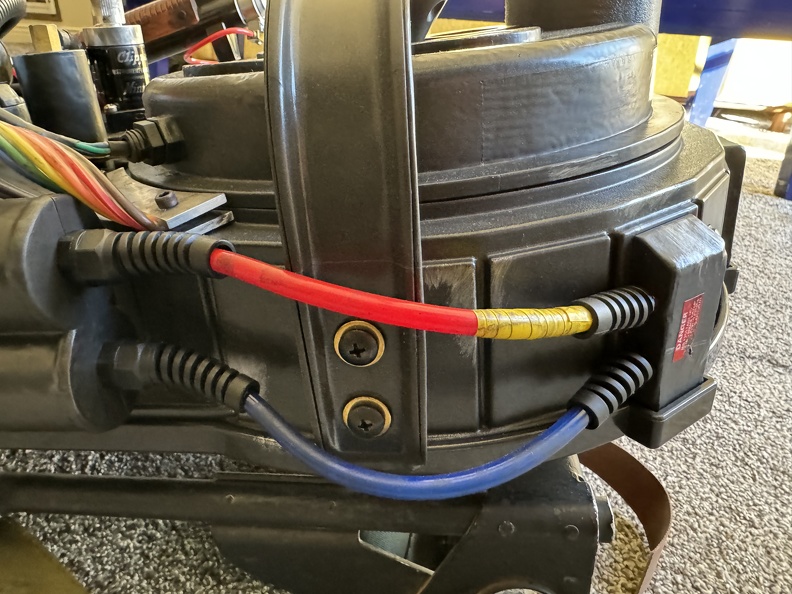
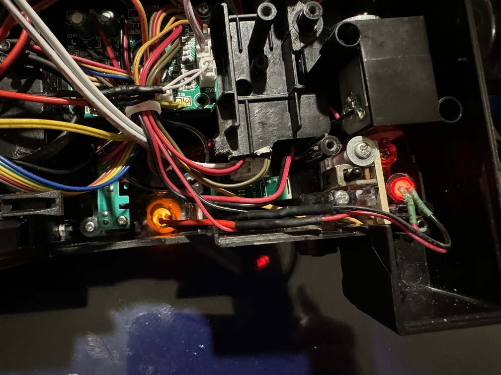
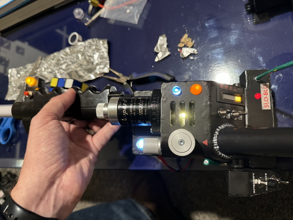
Here's a few detail shots, though, of things as they are now. (except the wand hook... I took these before that upgrade)
I want to tweak the spiral-wrapped wires here to show them off better, but this is still ok for now:
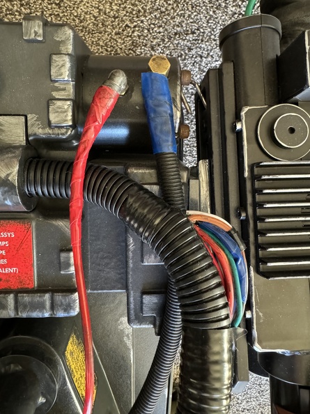
The Phoebe wires, stock (until I get a chance to tear them out and redo all that):
I might also make some adjustments to the wire bundle that sticks out... this is a little too even, I think:
So all in all, things are reasonably good... something is up with the NinjaTunes board, although it mostly works fine. It ran my pack for a good 6 hour day at the Con, and still had a good amount of juice left. I need to do a real burn test to see how much longer it will actually go. Jukebox mode seemed to work, too... I only played the first song on the list, walking around the Con at one point, but that was fun, too. (Although the need to pop the pack open to trigger that mode was not convenient... I may end up relocating those switches so I can get to them)
The current NT issues are this:
1) It seems to never fully turn off... one blue LED at the bottom of the bar graph stays lit continuously, if it has power (maybe it turns off eventually?), and I can see there are some blue lights on inside on the board itself, too. Switching off the battery with my battery kill switch works, of course, so I have a workaround for now.
2) During home testing, the board picked up the overheat and did it's thing, as expected. (alarm sounds, pack shuts down for a beat, then restarts). But while walking around the Con, the pack didn't seem notice... the wand shut down as usual, but the pack just kept going.
I'll reach out to Konstantine and see what he has to say. Neither issue makes it unusable, as the core functions are still good, but it would be nice to have all that working as it should, reliably.
Wow. Looking at and reading what you’ve done to your pack is amazing, intimidating, and humbling. Got a life-size Spirit Pack this November as an early Christmas gift and have been modding it since. We’ve definitely done a few similar things and I thought that was cool, but good grief. The effort on display here is awesome.
Winaiden wrote: ↑January 1st, 2024, 7:51 pm Wow. Looking at and reading what you’ve done to your pack is amazing, intimidating, and humbling. Got a life-size Spirit Pack this November as an early Christmas gift and have been modding it since. We’ve definitely done a few similar things and I thought that was cool, but good grief. The effort on display here is awesome.
Thanks for sharing!
Happy to serve as good example... or at least a horrible warning! LOL
I look forward to seeing what you do with your pack, be sure to post a thread!
Sooo... I've been busy, I swear LOL I just haven't had a lot of real progress to report, waiting for various orders to come in.
Up now is Wand upgrades. A few pack upgrades remain (particularly the wire shroud around the Clippard), but they're on hold until my Redman motherboard comes in. We're in February now, so hopefully soon? (Orders were supposed to close 2/1)
And after getting all ready to do a bunch of wand upgrades this weekend, of course, a few days ago Hasbro decides to drop the 84 version of their Wand, so I ordered that, and now it's not coming until mid-week.
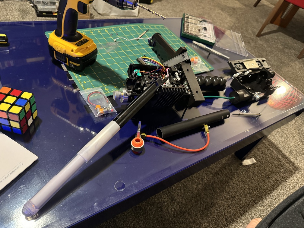
Still, since I had some time blocked out this weekend, I got some stuff done.
Let's start with parts for planned upgrades, though, shall we?
First and foremost, we have the metal side knobs. courtesy of GBFans:
I decided the other metal bits (the top adjustment knob and the knurled knob on the front) are actually accurate enough, and already metal, that it's not worth swapping them out.
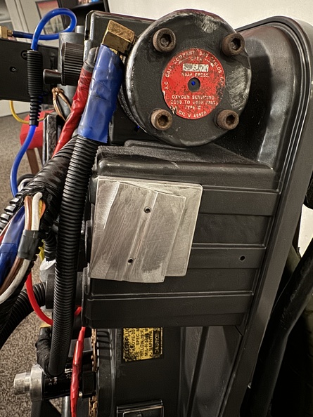
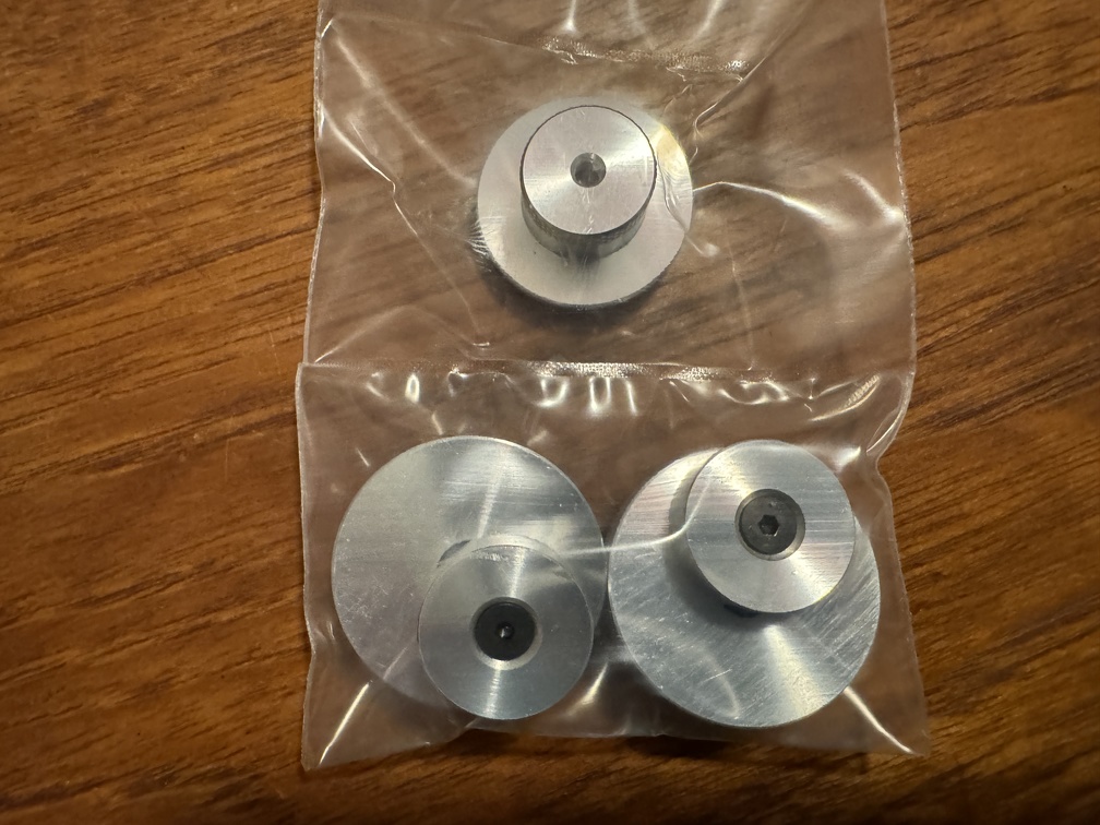
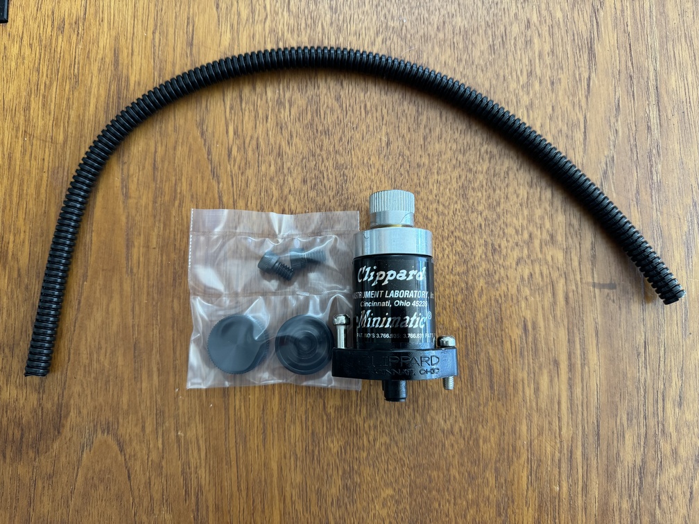
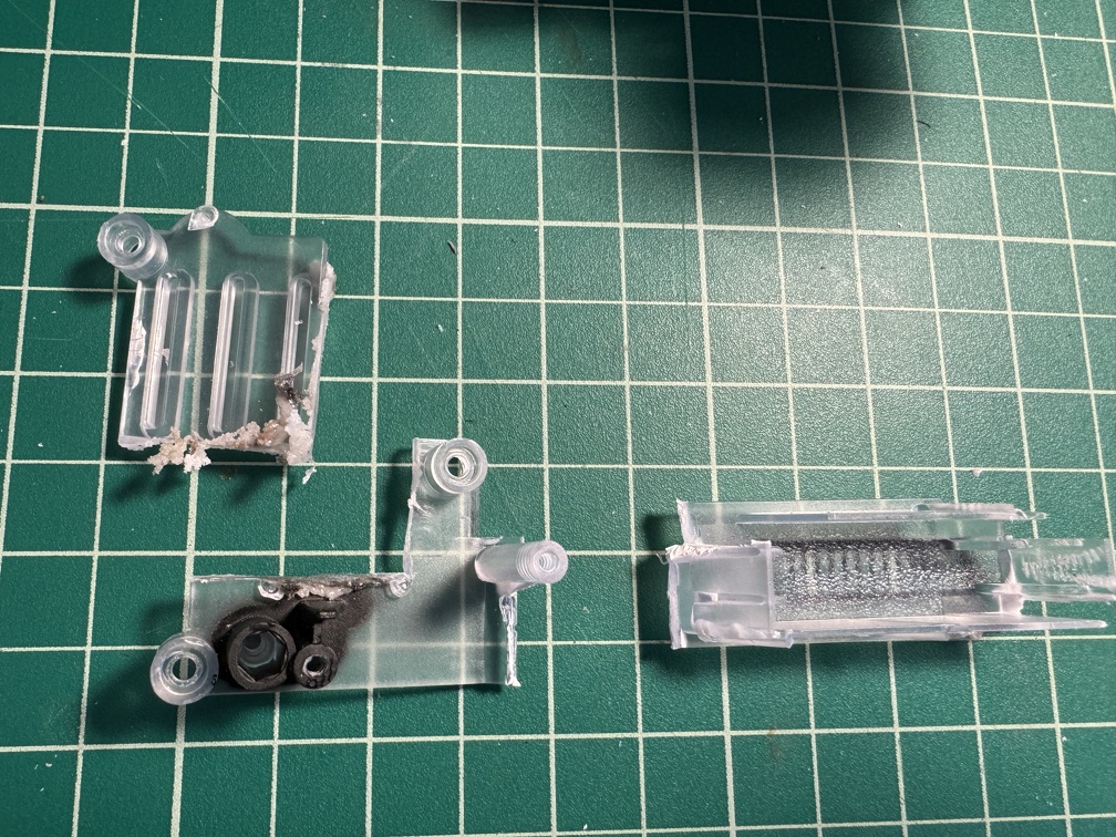
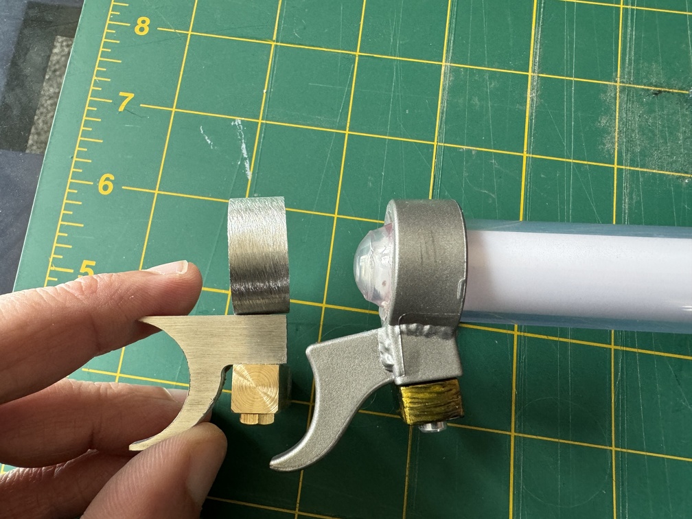
Next, I have the 701-R Clippard valve, also courtesy of GBFans. (That split loom will go on the pack, too... probably... and the knobs are to upgrade my Spirit goggles, once I'm ready to wade into that rebuild)
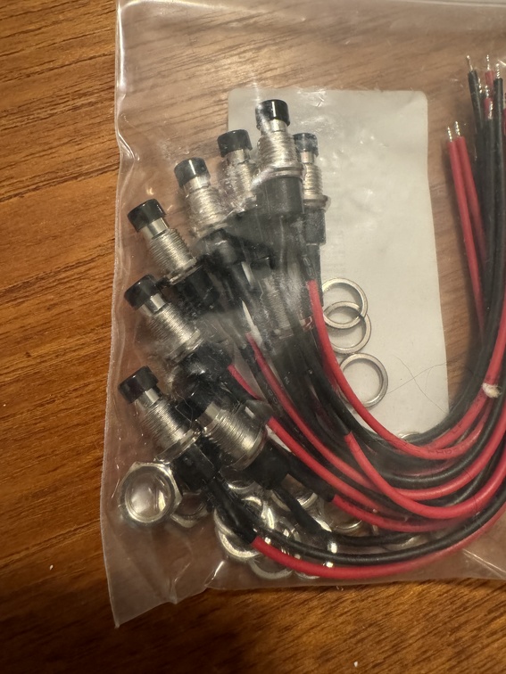
I also have these SPST switches to upgrade the awful plastic rod on the ear of the Wand, up by the mode switch:
BUT, all these bits and bobs are basically planned to go into the "final" wand, which I'm using the 84 as a base, so I can't do much with them until I get that in hand.
HOWEVER, a buddy pointed out a mod to the tip of the orange-tipped Spengler wands that I wanted to actually do. And then another occurred to me. Honestly, these mods are so easy I feel like most people should consider them. They really add something, over the stock wands, at minimal to no cost and effort.
Hasbro Wand Mod #1 of the Day: (This applies to both the Spengler and 84 wands)
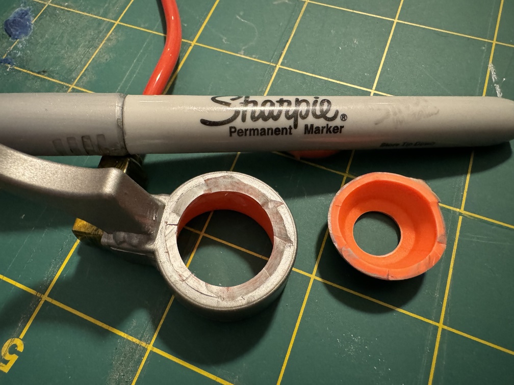
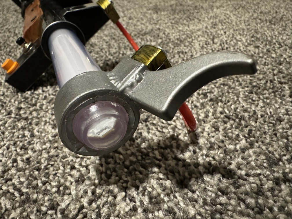
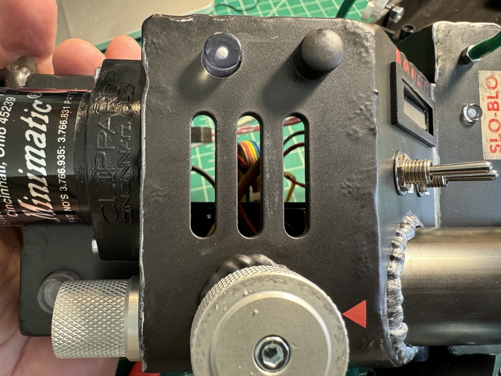
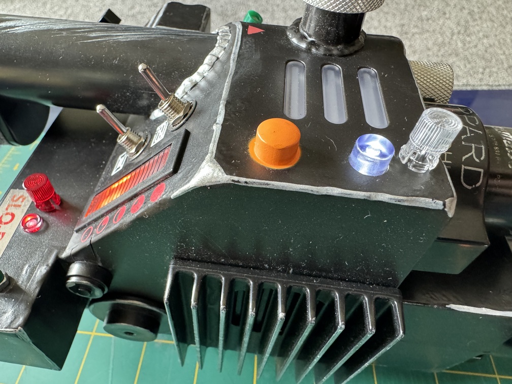
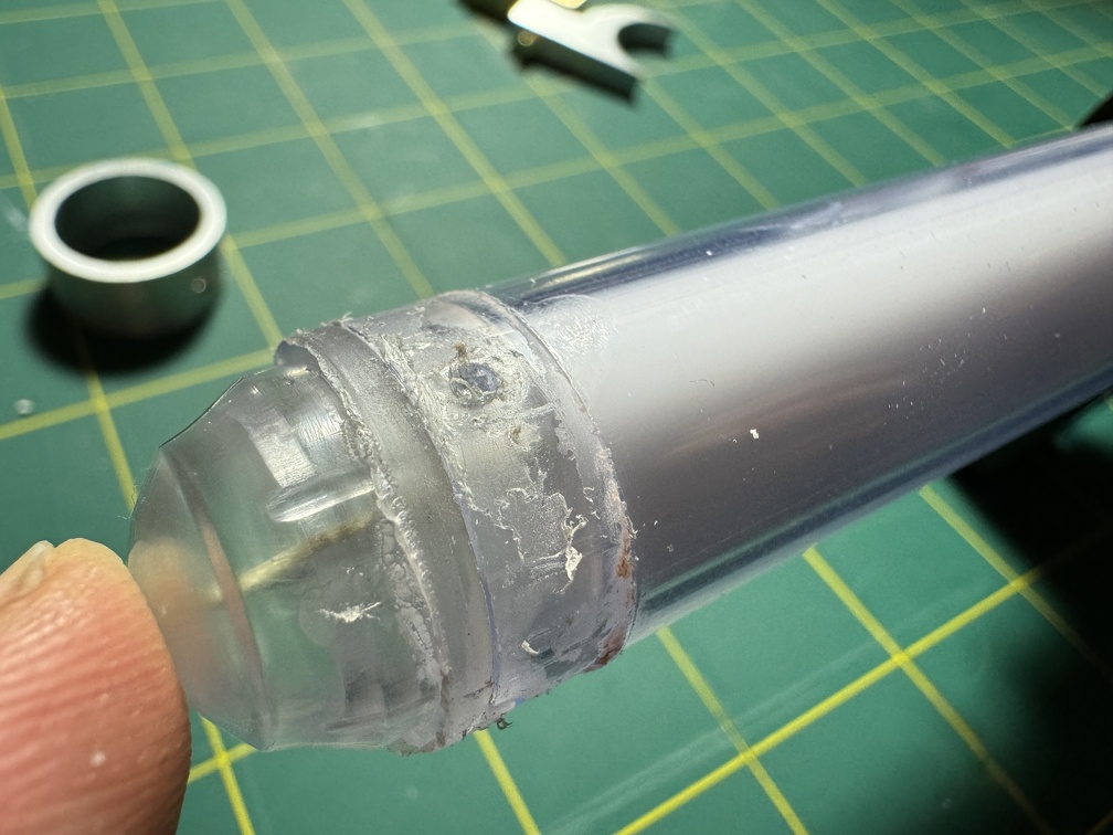
If you have a Spengler wand or even the new 84 wands, they have a weird cap at the tip of the wand, attached to the "metal" ring and trigger setup. On the early silver-tipped wands, it was easy enough to ignore, but really hard to ignore when they changed to bright orange tips instead. Many people just color this silver (as I did, initially). Silver Sharpie is a pretty perfect paint match, even, so it's stupid fast and easy:
BUT more accurate is to cut that cap at the end off. With the orange ones, you still need to touch it up, as the whole thing is actually orange plastic (silver painted on), as opposed to the silver plastic of the early models.
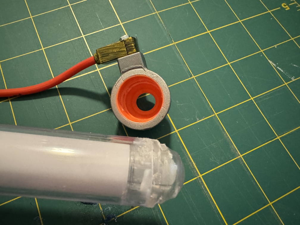
Step 1 is to remove the whole tip. That stuff is literally rubberized plastic, so it comes off pretty easy... some will literally pull right off, others (like mine) are glued on somewhat, and are harder to just pull off. But it only took about 1 minute with my wife’s hair dryer (on high) to warm up the tip enough that it came off quite readily. Anyone should be able to do this, no issues. The whole thing comes right off in one piece:
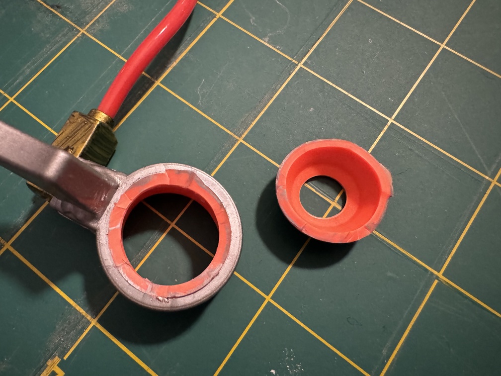
Next step is to use a sharp blade (utility knife or exacto) to cut the cap off. Just slice that cap away carefully at the seam. It cuts easy, being soft rubber. Note the orange interior.
I grabbed my silver Sharpie (which was getting a little dry... I'll hit this again later) and threw down some paint, and you can see how nicely it matches.
Then just glue the ring back on. I recommend doing this with the extending tube in the closed/retracted position, to make sure you're positioning it correctly (and straight!) Note when you’re gluing back the ring, I’d be cautious about using regular superglue (aka CA glue). CA glue is notorious for causing hazing on any nearby clear plastic. (Sort of a white foggy film). I’ll be using e6000 on mine, to make sure this doesn’t happen.
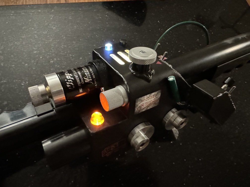
I may clean this up a little more later, or may not bother, since I'm planning to upgrade to metal anyway, but here's the end product:
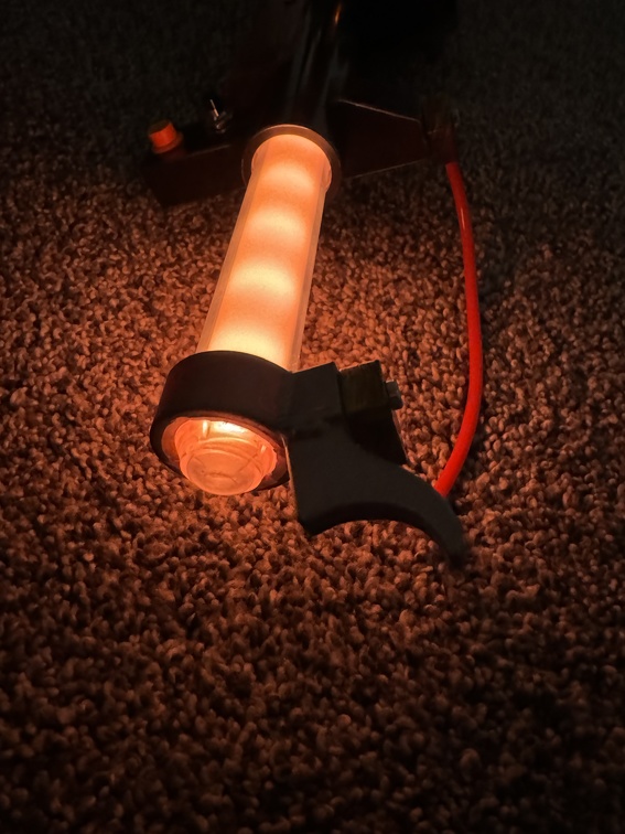
And lit:
Easy!
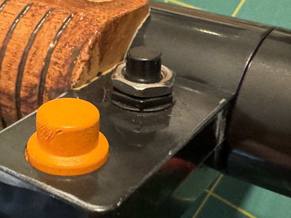
Hasbro Wand Mod #2 of the Day: (This also applies to both the Spengler and 84 wands)
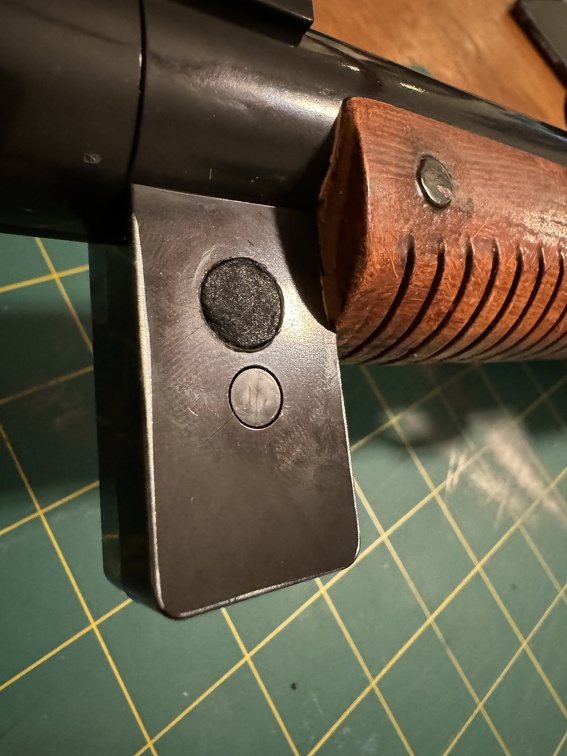
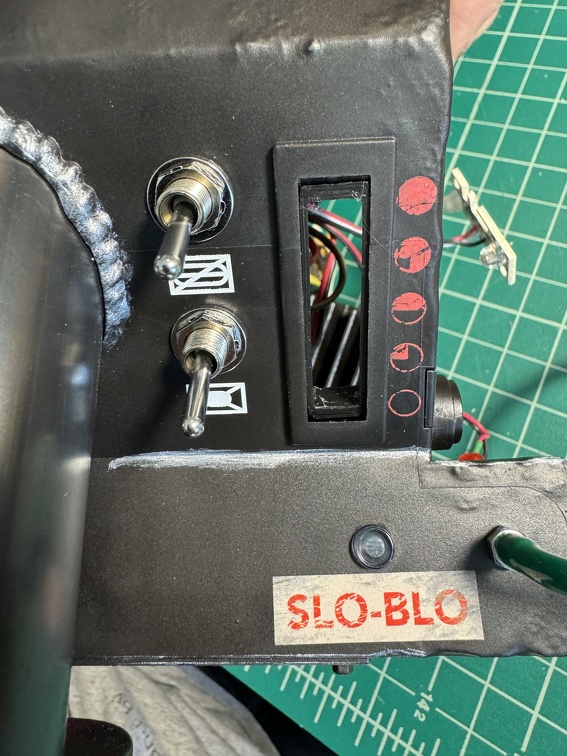
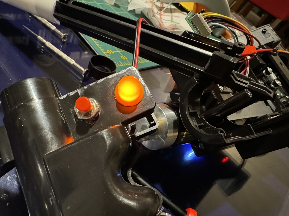
Since I had a whole bag of these switches, and only need a couple, I decided to install a "Sacrificial" dummy switch, to replace the solid plastic lump on the ear. (By the orange mode switch) This solid stick of plastic has always bugged me, and the real deal looks SO much better. Repeat of the photo above, but it shows the black fake switch nicely:
This mod is non-functional, currently, but maybe could be made functional, IF I actually take apart the wand and install from inside, instead of drilling one extra hole. Then you can do some extra wiring and install a real LED, lots of stuff. Today, I wanted quick and easy, and I did NOT want to open and tear down the wand, so the one extra hole on the bottom (easily plugged) enables that. This is technically a destructive mod, but it’s pretty darned mild. Two holes, really.
Tools used: Utility knife (or Exacto), Drill with 15/64” and 3/8” drill bits (or metric equivalents), filling clay foam or putty/milliput
Switch used: Twidec/10Pcs 1A 250V AC 2 Pins SPST Black Normal Open Mini Momentary Push Button Switch with Pre-soldered Wires PBS-110-XBK https://a.co/d/fpxbmuS
(Note you can get black switches, or mixed black and red, depending on which wand you’re replicating)
I did a quick test-fit of one of the switch lock nuts, and sure enough, the real nut lines up perfectly with the molded black plastic one, and this will match things nicely.
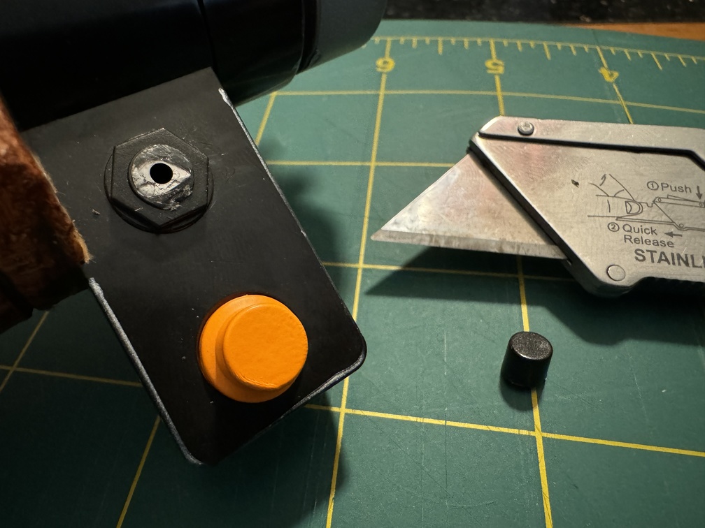
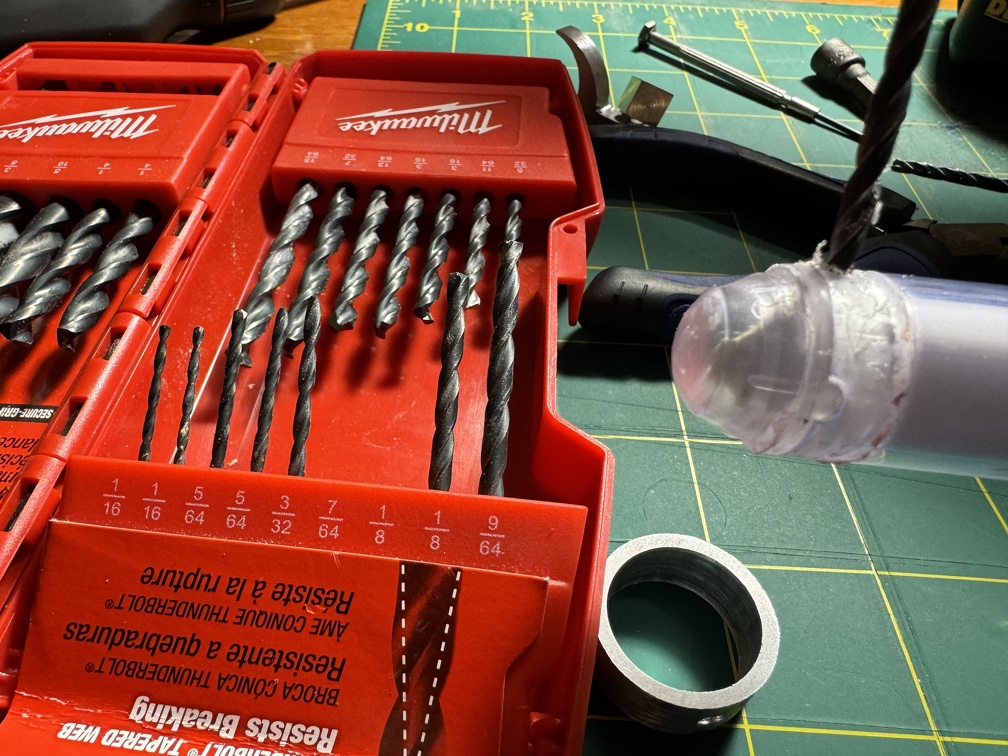
Step 1) Cut off the black plastic nub (fake switch, just the top cylinder, not the fake nut yet). A small hole will be revealed.
Step 2) Drill the new hole where the one you just uncovered is. Ultimately you want to match the switch body, nice and snug, which seemed to be 15/64 for me. You May want to start small and step up to the 15/64 size in increments, to keep it nice and centered.
Step 3) Once you’re happy with the top hole, Carefully drill straight through and out the other side (bottom of the ear). (Same 15/64 bit) If you look inside, you now can probably see the thin white wires that go to the orange mode switch.
Step 4) Clean up the fake nut on top (carefully cut it away with your knife).
Step 5) Drill the larger 3/8 hole in the underside, so the whole switch can fit through. Be careful… those wires are inside for the orange switch. They aren’t really in the drill path in any I’ve seen, but you still don’t want to thrash around wildly in there. Also make sure your bit doesn’t bite the plastic and suck itself all the way through and make the top hole too big.
I'd do a quick test fit, at this point. You should be able to get the switch in place through the new bigger bottom hole, and see how far those contacts extend out the bottom. I spent a minute messing with the wires, to see if they could be stuffed inside for future but no, not really.
Step 6) Cut down the electrical posts / contacts at the bottom of the new switch, so it can fit in place without wires sticking out the bottom. (NOTE: If you are able to open the wand entirely, you could skip steps 5 and 6, since you’d have full access from inside the ear, the switch could be made functional)
Step 7) Remove the nut and washer (if present) from the switch, and thread the switch in, from the larger bottom hole, so the top protrudes through the top hole.
Step 8] Put the washer and nut onto the switch from the top, and tighten snugly. (Take a beat to admire the new switch!)
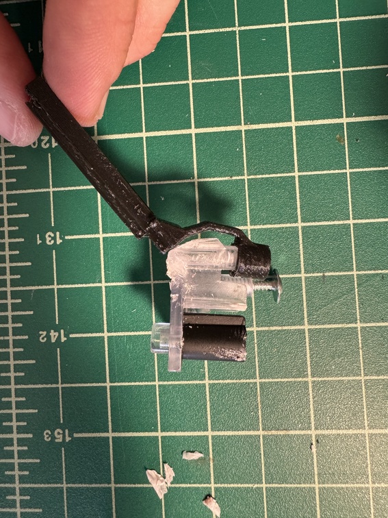
This is what you're left with on the underside:
Step 9) Fill the hole in the bottom with putty or craft foam, and paint if needed. I used a plug of black craft foam clay, so I could easily remove it later if I want, no real finishing needed, as it’s barely noticeable. Another option would be using some of the accurate heat shrink tubing to cover the whole thing, then you really don't need to worry about the hole.
This short shows the plug material in it's worst shape, with light reflecting on the shiny plastic but NOT the plug. How often to people look closely at the underside, though? It's honestly so not noticeable I considered just leaving it open. The foam clay, being so easy to pull back out, seemed like a good compromise.
Besides, this is a more accurate idea of what people see, if they EVER see the underside, there. A little sanding and paint would disappear it even more. You could always use something more permanent like Milliput or SteelStik, too, but again, I wanted the ability to easily get back in there, if/when I want to replace this switch with a functional one.
Now that I've done all this lovely work on my Spengler wand (ok not THAT much, just the silver tip and the pushbutton), my 84 Wand arrived, of course.
Time to start the REAL mods. Mega update, coming your way!
Hats off to Hasbro for having the cajones to ship the 84 wand inside a MUCH larger box, with the tape slit open (on the inner wand box, that is) and without a lick of padding inside the box. WTAF. Fortunately, everything seemed intact inside.
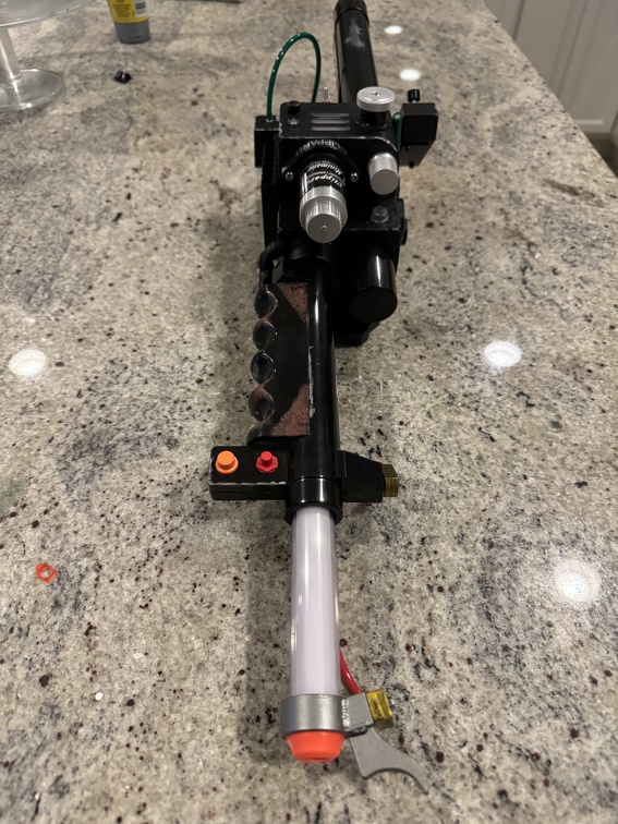
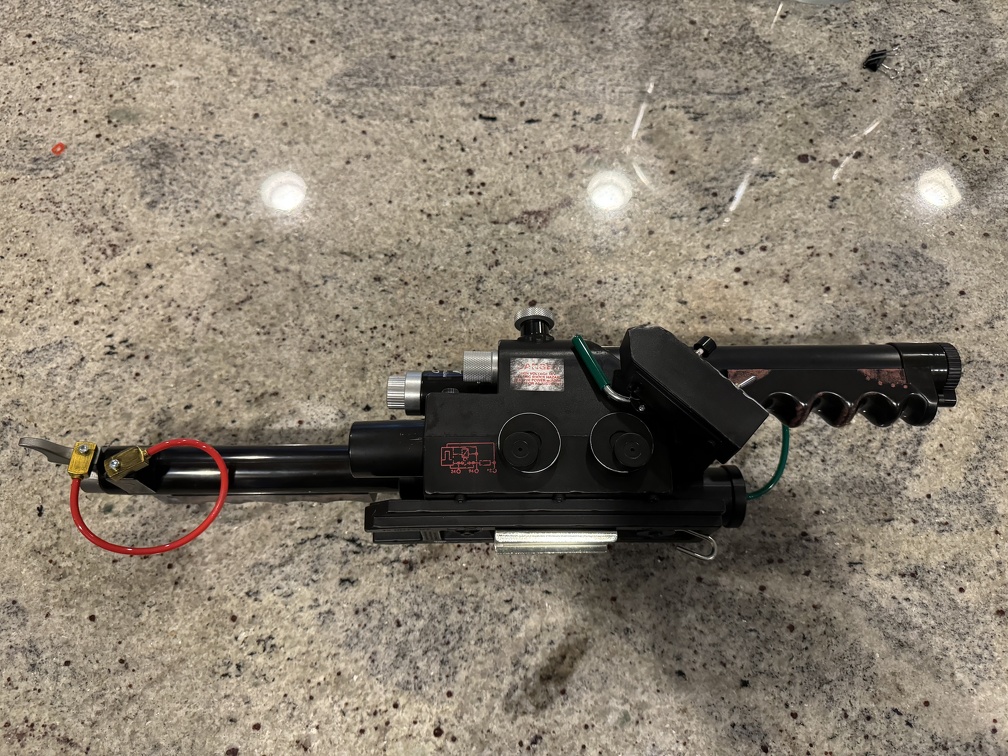
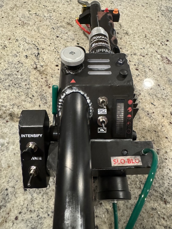
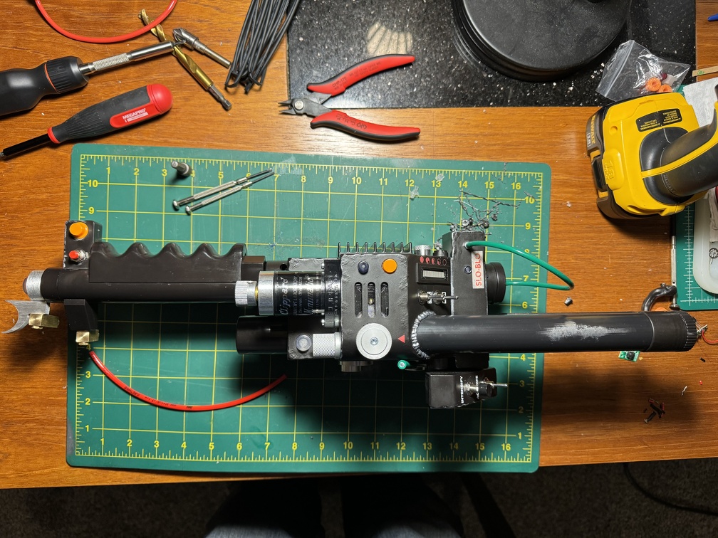
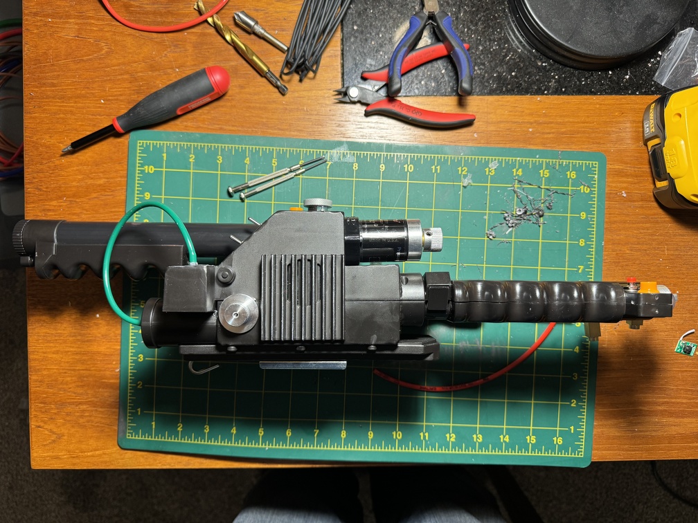
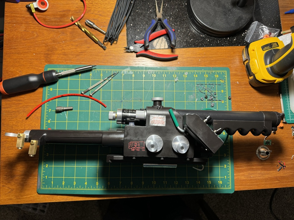
First, a couple shots of stock wand, for posterity:
Front:
Left Side:
Back:
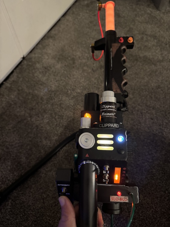
Firing:
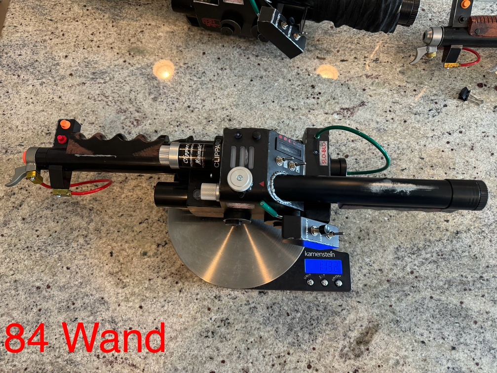
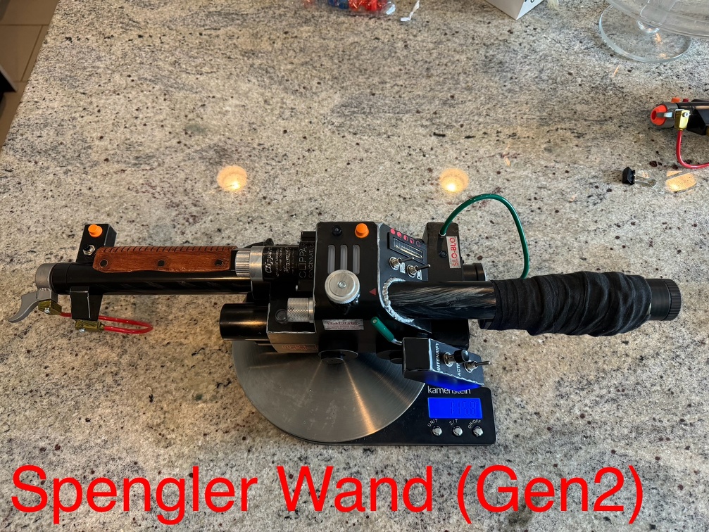
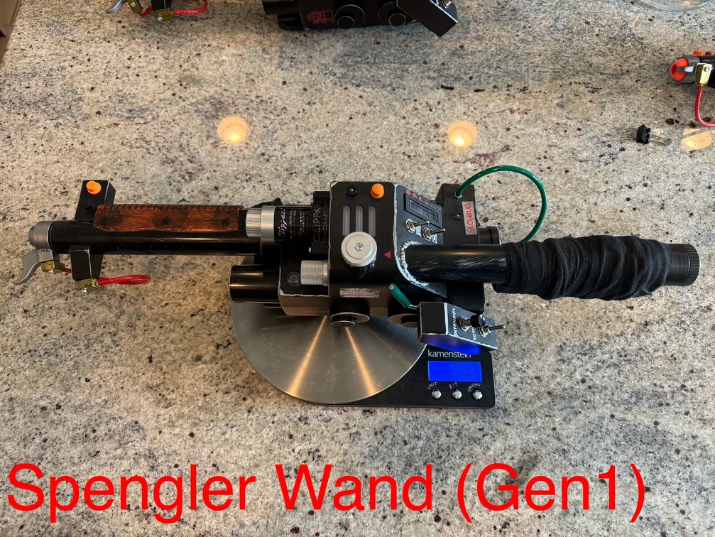
And some wand weight comparisons, since I posted this on FB and goodness knows that'll be impossible to find in 2 months (and not everyone is on FB):
84 Wand [100% stock]: 1 lb 13.2 oz
Spengler Wand (Gen 2 Orange Tip) [Mods: handle tape wrap, orange tip cutoff, 1 real pushbutton]: 1 lb 15.8 oz
NO BATTERIES inside any of those, just the empty sleds.
I honestly suspect the 0.2 oz difference between the Spengler wands was mostly due to (a) the added hockey tape wrap, and (b) a small difference due to the weight of the different grips. I doubt that switch weights enough to matter.
Note for other comparisons: Three AA Duracell batteries weighs 2.5 oz in case someone compares these numbers to someone else's, that includes battery weight.
Mod #1: Paint
Mod #1, if you can call it that, was removing the godawful weathering Hasbro put on these wands. I get what they were going for, but wow, they must have outsourced and used the lowest bidder for the weathering this round. The brown handle weathering is utterly non-realistic and poorly adhered... it literally wipes off with zero effort using a paper tower and some isopropyl alcohol. You don't even need to wipe it hard, it comes right off. I think this stuff would come off on its own with just hand sweat, so I'm glad I removed it. I'll repaint that at some point.
The silver paint is adhered better... you have to rub it moderately hard to remove it with the same paper tower and isopropyl alcohol. But WOW the silver paint job is even worse than the brown, and that's saying something. Some "wear" on the edges is fine, but then they literally have straight silver paint lines in random places that look NOTHING like wear. (There's a nice looking wear mark on the back of the handle that is screen printed on... that's actually pretty nice. But everything else is astonishingly bad, compared to previous weathering jobs Hasbro has done.). Still, not too difficult to remove. Or just paint right over, your call.
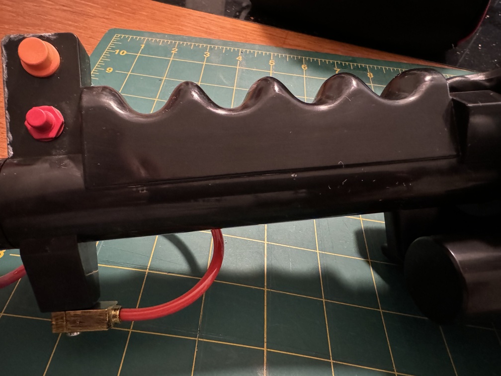
Before:
After:
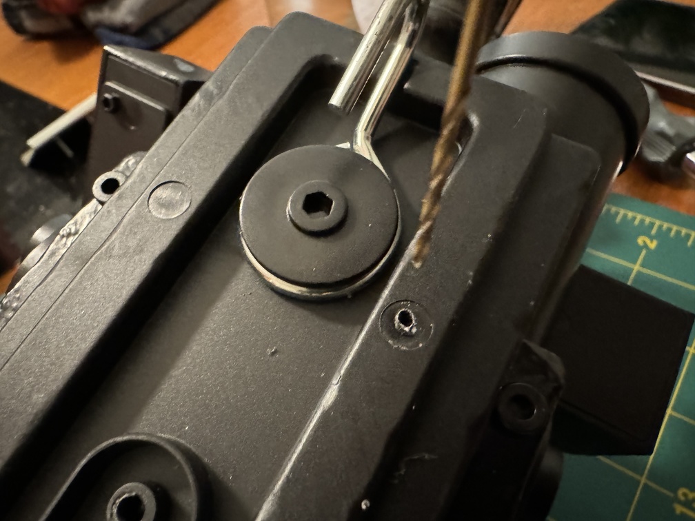
Mod #2: Metal Discs
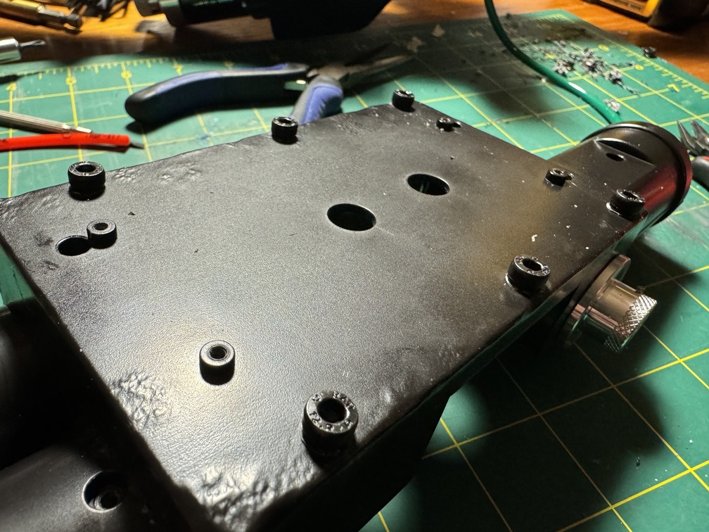
Next, it was finally time to get inside. As many others have noted, this just involves drilling holes into the 5 capped screw hole covers on the bottom of the rail, and either hooking out the plugs, or just drilling them out entirely (carefully, don't hit the screw that's 1/4" inside under that plug!), and unscrewing them to remove the rail.
Then 4 screws (the barrel screw is way longer) and the bottom opens up, easy peasy, and you can finally see inside:
Now, one thing I forgot to document. There is a plastic plate underneath the barrel at the bottom of that pic, which keeps the wirey bits away from the slidey-slammy moving barrel bits. That gets cut away. Pretty simple, but you can't see it under the barrel in this pic, and I forgot to take a clear one with the barrel out of the way, showing the plastic, before and after I hacked it off with nippers. Plenty of videos on YT showing these teardowns if you want to see that happening.
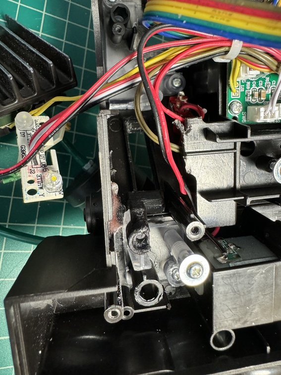
One bit of warning: I unscrewed the stock controller board to move things out of the way, and started unplugging the cables that are plugged into connectors on the PCB. No problem, but BE CAREFUL: When removing the two wire connector that goes up the barrel (I assume to the switch in the front ear, or maybe to the tip LEDs?) the WHOLE SOCKET lifted clean off the board with the connector itself. Thankfully I was able to carefully push it right back into place, and everything still worked. But use extreme care when unplugging things.
(btw you can see some of the plastic separation plate that I later hacked away here, ref to a couple paragraphs up)
Moving on.
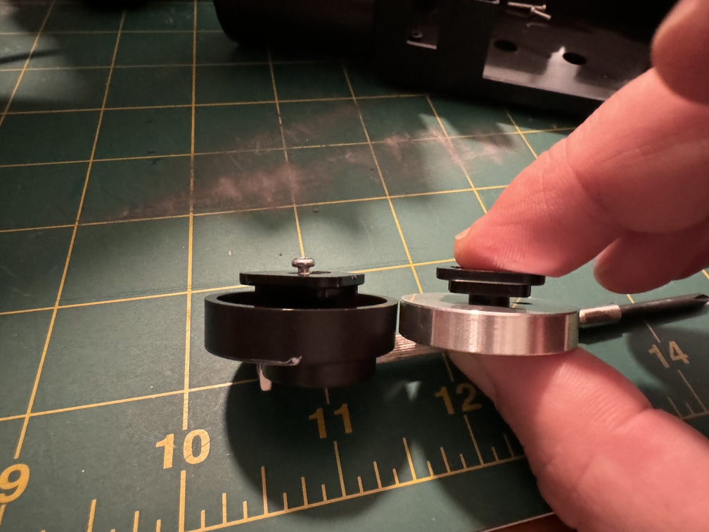
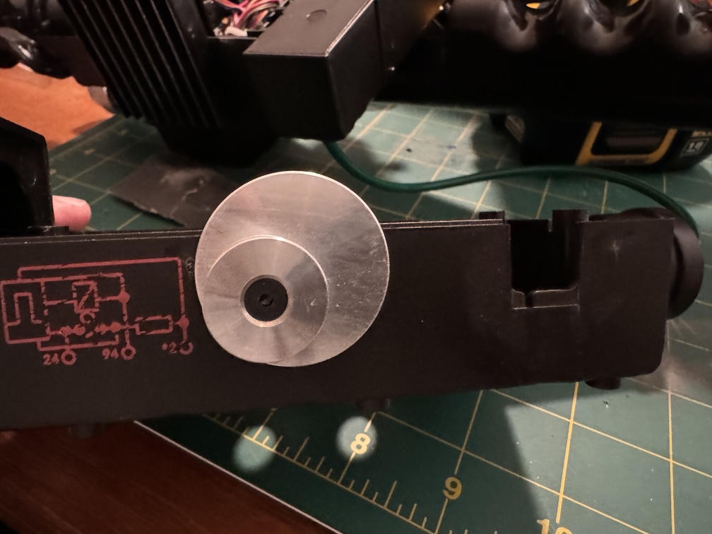
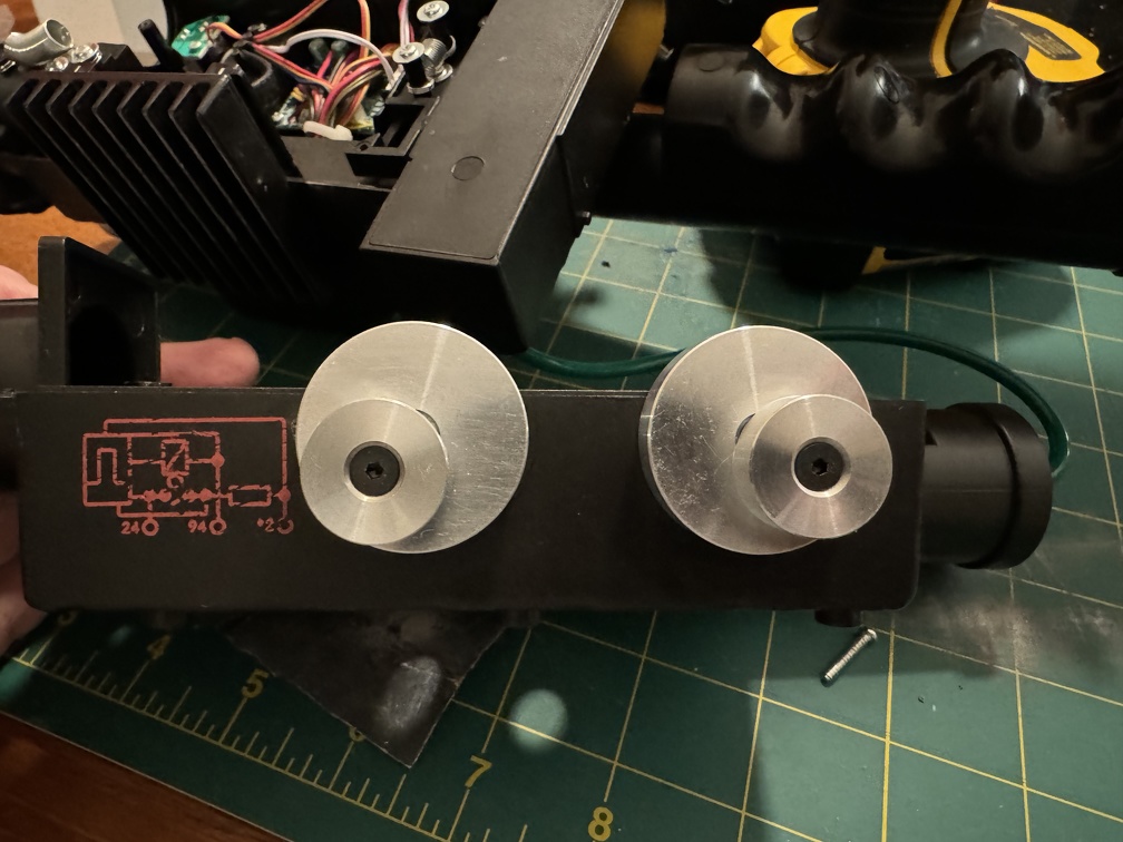
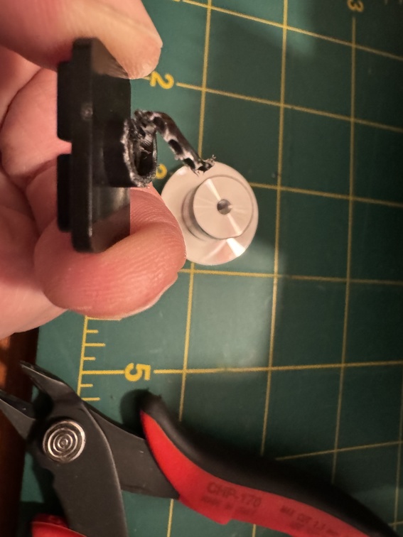
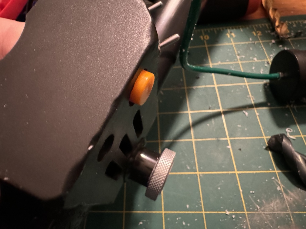
The two plastic side offset "knobs" are the first to go. VERY easy to replace, just unscrew the screw, and the disc/knob thing comes off the little plastic keyed tab that holds it in place. There's a plastic post that extends into the plastic knob a little bit which needs to be sanded flush, since it won't be extending into the metal disc, but then the metal part just screws onto the plastic tab, same as the original part did. Repeat for both of them, and you're done.
Plastic tab it too far from flush on the metal one:
The knurled disc on the other side of the wand is mostly the same, except the too-long post extends the opposite direction for the GBFans-provided screw to reach. A quick snip around with my flush cut snips to take a little off the end, and it screwed right in perfectly.
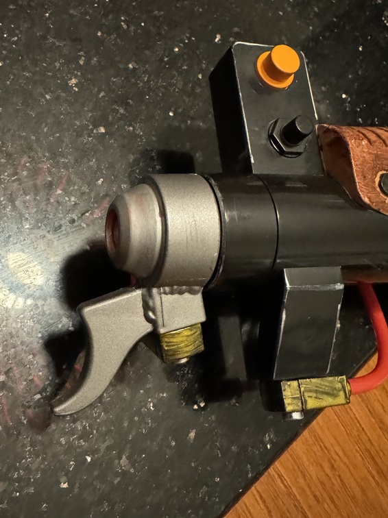
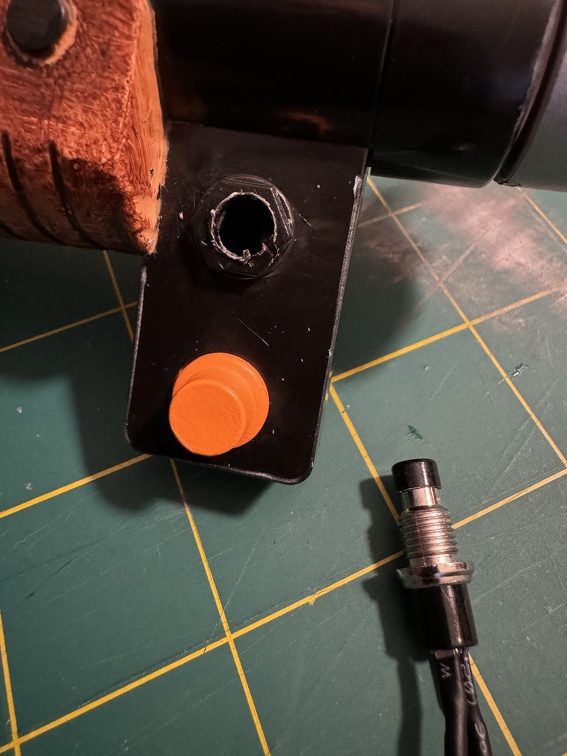
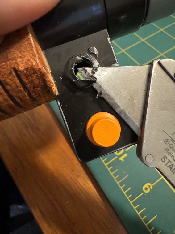
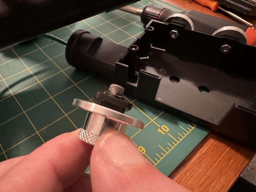
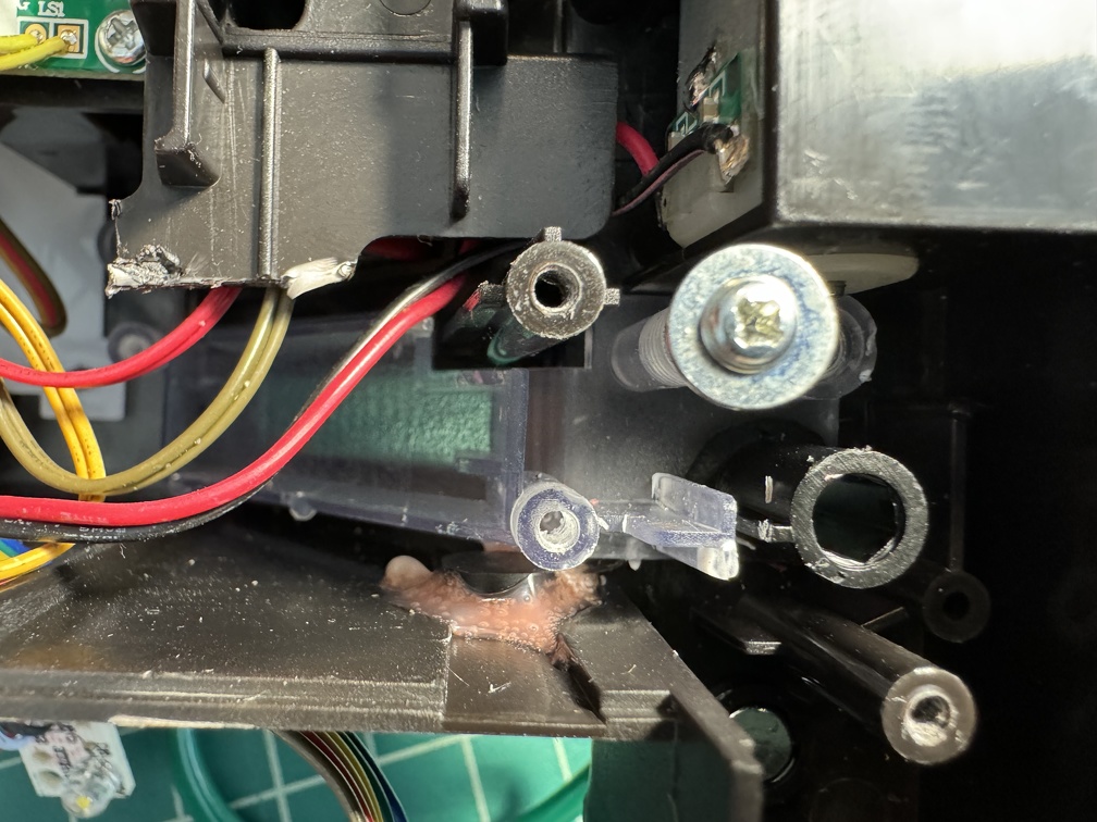
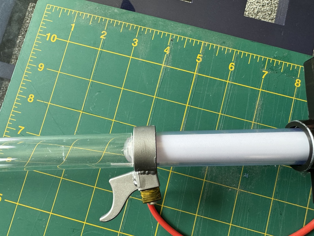
Mod #3: Clippard
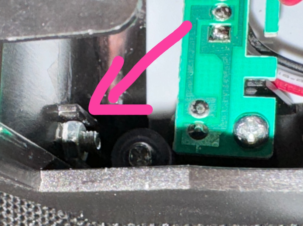
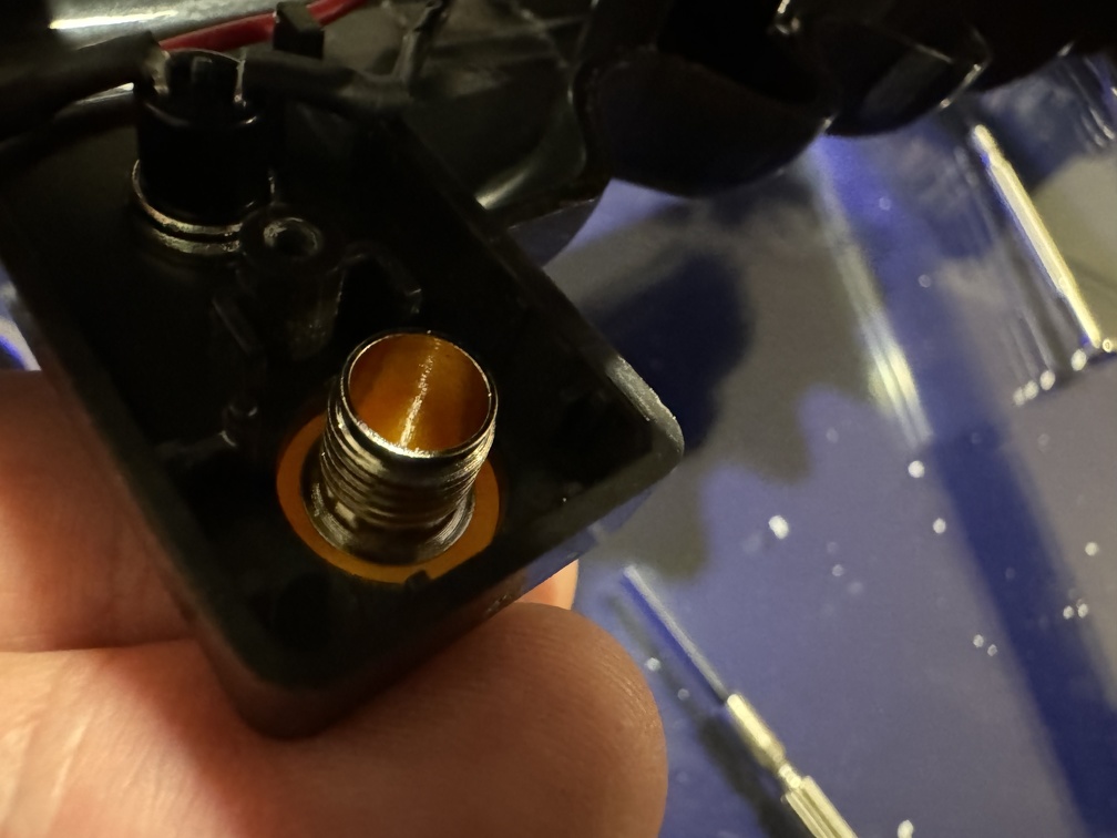
Next up, the real Clippard R-701 valve install. Awesomely, the main pair of holes in the fake valve base actually line up nicely with the real base! Of course, the real valve has a round protrusion out the bottom center, with a keyed ridge molded in. Not a big deal to drill a hole in the middle, and use a needle file to cut a slot for the little keyed part, and it goes right on. Note when you're unscrewing the OEM valve, the nuts inside are only loosely held in place. If you're careful, you can probably keep them in place, and just screw right back into the same nuts. If you push even a little too hard, you'll pop them off and have to fish around in the depth of the wand to pull them out. (Ask me how I know LOL) Still, not too hard to get the real thing screwed in, and secure held by nuts on the inside.
Note slot holding nut in place (somewhat):
And that's done. SO PRETTY!!!
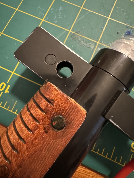
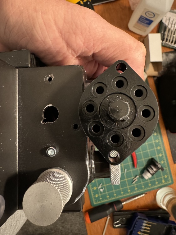
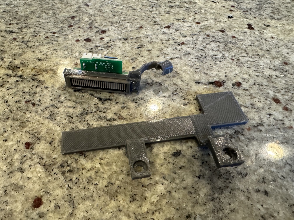
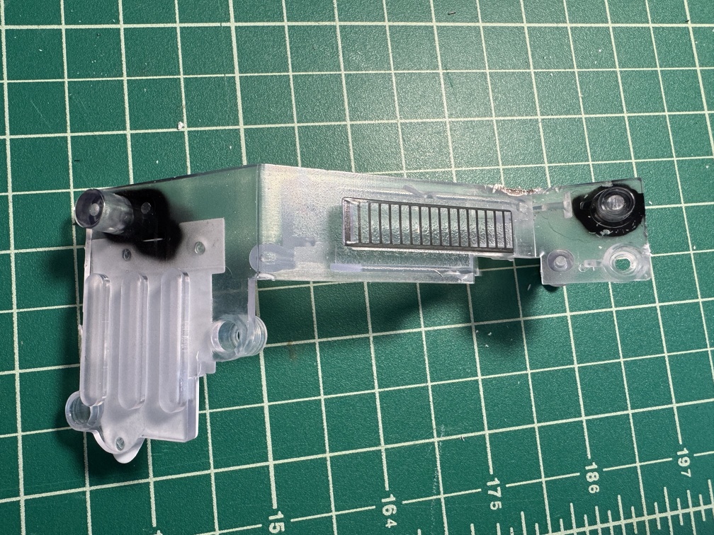
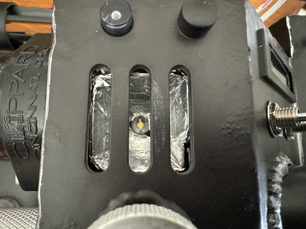
Mod #4: Frutto Tech Bargraph LED and Vent Hole Plate Removal
One of my most anticipated upgrades! I purchased Frutto's upgrade kit, and 3D printed the bracket as well as the replacement panel to protect the wiring from the wand extension mechanism.
(I just realized this pic was the first draft print of the LED bracket... the final bracket was from black PETG)
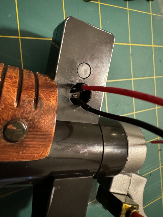
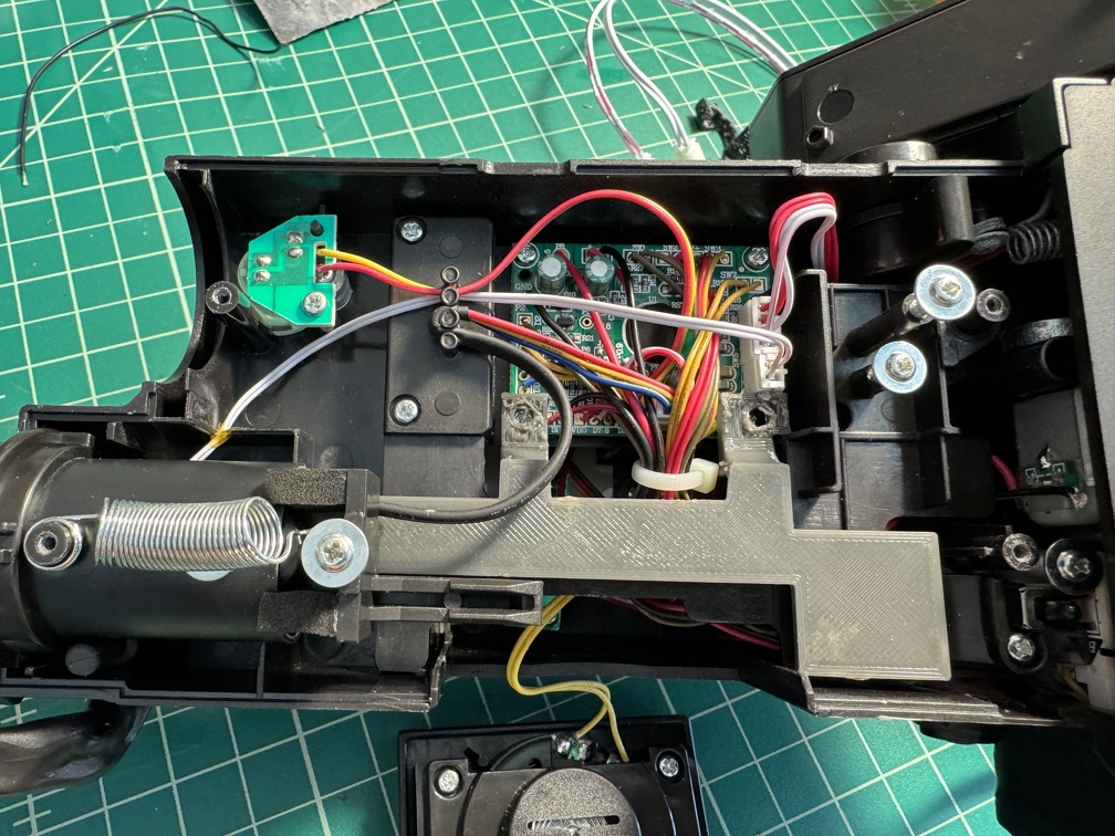
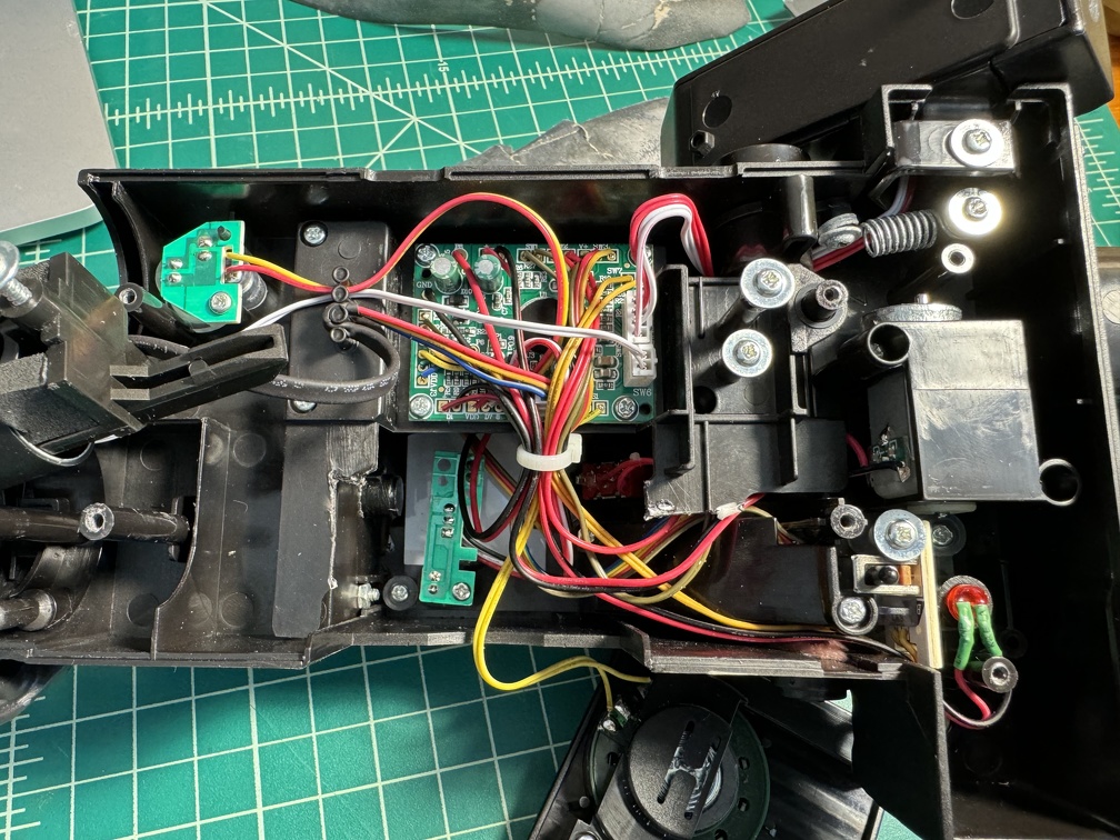
A quick test fit shows the plate seems to fit in there nicely, piggybacking off two of the mounting screws for the main board. (Release mechanism already removed, on the right side)
The bottom panel of the long rectangular box has to be opened as well, so the LEDs, switches, and top part of the whole bargraph/vent hole assembly can be accessed. (Side note, this is a good "after" shot showing what the interior looks like once that panel I mentioned above is trimmed away)
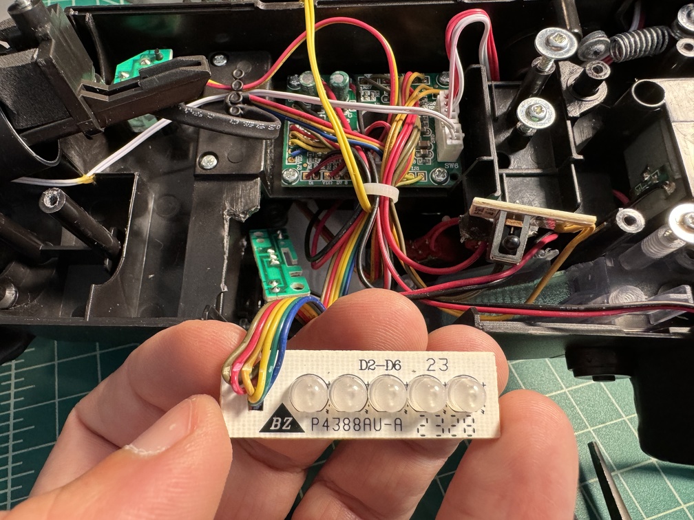
With the wand nicely laid open, popping the stock bargraph LED board out was straightforward. A little scary to cut through the wires going to that board... I wish they had used a connector!
Removing the huge, one piece plate that holds the inserts into the top vents and the stock bar graph was ... not easy. Three screws down below, around the vent holes (I guess that's technically the top of the wand, but we work on it upside down) plus two LED boards that two of those screws hold in place (top panel LED and the interior light that shines up the vent holes), and then three more screws above (plus an LED that needs to be carefully lifted out), and then Hasbro apparently decided to use some sort of resin cement (aka pink goop of doom) on the side that was tough to scrape away before the part would finally come out.
See pink goop of doom, bottom center:
But I got it out, using a needle file to just scrape at it over and over until I got through:
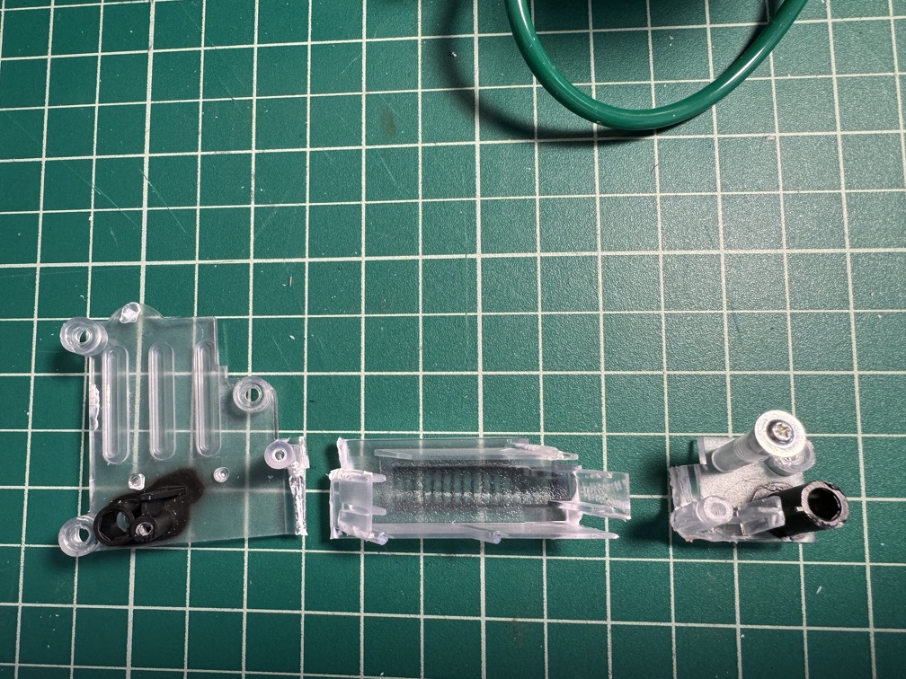
And finally the whole part was cleared and pulled free.
That part needs to be carefully cut into three pieces, retaining the right screw posts on each, so everything can be screwed back in properly, but the bargraph part comes out.
And for the vent plug delete, one of those pieces needs a further bit lopped off. I used flush cut nippers for most of the hacking, but this last bit needed a Dremel's cutting wheel to avoid cracking the plate wrong. But once that part was cut away, the vent is free and clear, moving forward.
The bottom and top screw clusters are added back in (note this clear panel uses shorter screws for connecting to the body, compared to all the other screws in this wand), and the vent plug deletion is now complete.
Next I'll install the bargraph in the middle, between the two replaced screw pads (for lack of a better term).
The 3D printed mount for the bargraph will sit inside like this, with the little arm placing a screw hole atop one of the screw posts in that top cluster. (Actually that's technically the lower cluster, with the slo blo LED mount, once everything is flipped over, but this is how we're looking at it.). I had to cut away a bit more of the bottom right corner of the clear plate in this photo, so the printed LED mount could sit correctly.
I removed the LED bargraph from the mount and put the clear mounting plate back in place, along with it's LED, etc, and then placed the 3D printed bracket. Flip it all over, and you can see the little edges of the bracket inside the stock bargraph LED slot. (The Frutto unit is a little smaller than the stock Hasbro parts, clearly). I had considered painting this piece, but considering the little sliver that's visible, and how smooth this part is (being the bottom of the print that was on the plate), I won't worry about that. For now, at least.
And in place inside:
Place the bargraph inside, and this part is done. Be sure it's in there right-side up! It's easy to get turned around, when you're working on the wand upside down. For the Frutto barograph, in the Hasbro wands, you want the edge of the little circuitboard attached to the LED's back to come close to the side wall, not pointing into the interior of the wand. I unfortunately don't have a good pic right now, but I'll edit one in later if I remember, next time I have the wand open.
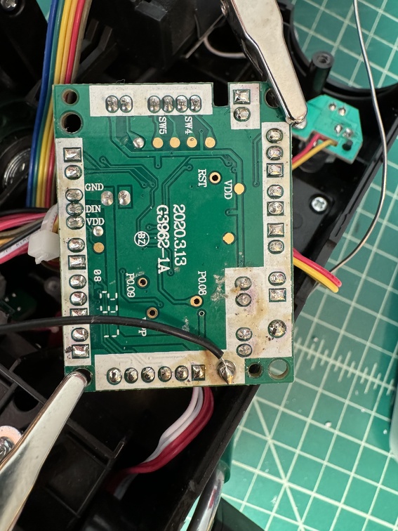
The one bit of soldering required by the Frutto LED is to attach a new ground wire to the back of the stock wand control board. Flip it over, and solder it to the back. (Pardon my un-cleaned flux). Note the new black wire. This new black wire will go to the screw mount wire block on the little sub-board that attaches to the bargraph via the two little ribbon cables. Also insert the rainbow wires cut from the old LED board, per the instructions on Frutto's site. (Also, connect those new JST ribbon cables... one of the sockets the each of the boards is marked SCL/SDA, so connect those two, and connect the unmarked pair)
SUCCESS!
Mod #5: SpongeFace Wand Keep-Alive
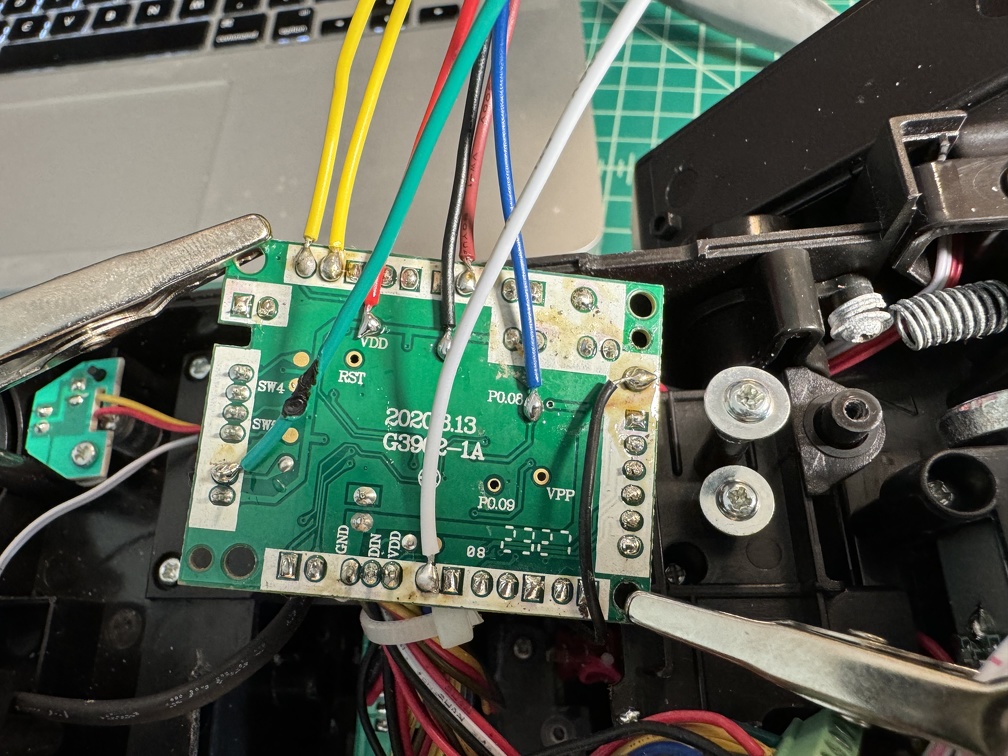
And for my last trick of the day, while I'm soldering things, next up is soldering the new wires to the back of the main board for my Spongeface Wand Keep-Alive. This is the newer version of the board, since a couple other people have confirmed it works with the NinjaTunes board in my pack. First test, though, is this standalone install.
Installation is pretty straightforward, yet not entirely "easy": Soldering 7 new wires to the back of the main board can be nerve-wracking. Fortunately that went fine, even though my soldering skills start to get a little shaky when we talk about more than connecting two wires, and start looking at PCBs. But I got them all on!
Check out all those new wires!
Once the wires are soldered on, you're good: The main board can be screwed back into place, and the plug can be inserted into Spongeface's add-on control board, and stuff should work.
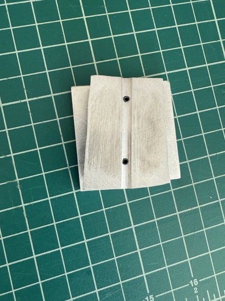
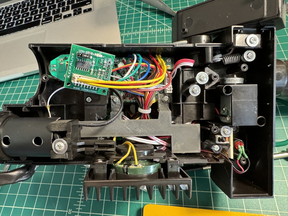
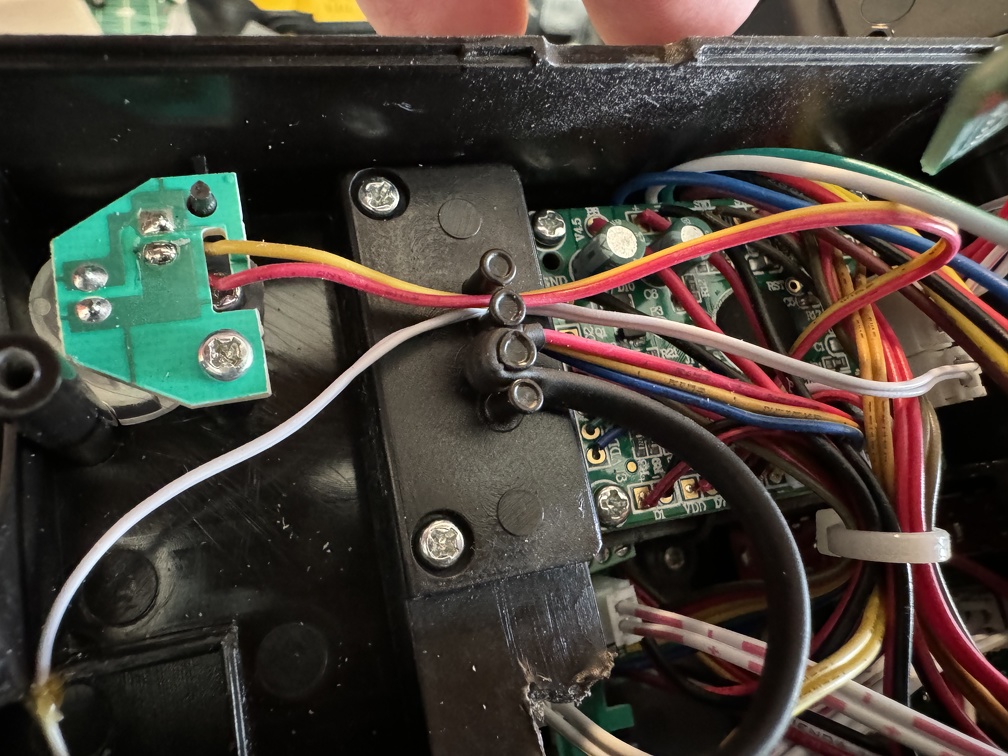
Also, I added the new panel that takes the place of the plastic panel that was hacked away in the beginning of these mods, to keep the wire-filled area separate from the moving spring-loaded barrel assembly.
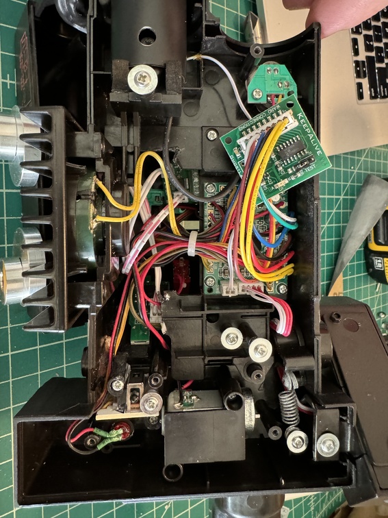
But now we run into a slight problem. The 84 wand has a slightly re-designed wiring block, compared to the prior wands. Those pegs now do a lovely job of protecting the moving barrel wires, compared to prior designs. BUT the 3D printed block provided by Spongeface that is supposed to mount on those pegs won't work anymore.
I'm reaching out to Spongeface for more permanent options. But for now, I just taped the little sub-board in place, and closed everything up. It'll do for now.
SO THAT'S THAT.
What's next?
More is planned. Painting and weathering, obviously, but I'm not there yet.
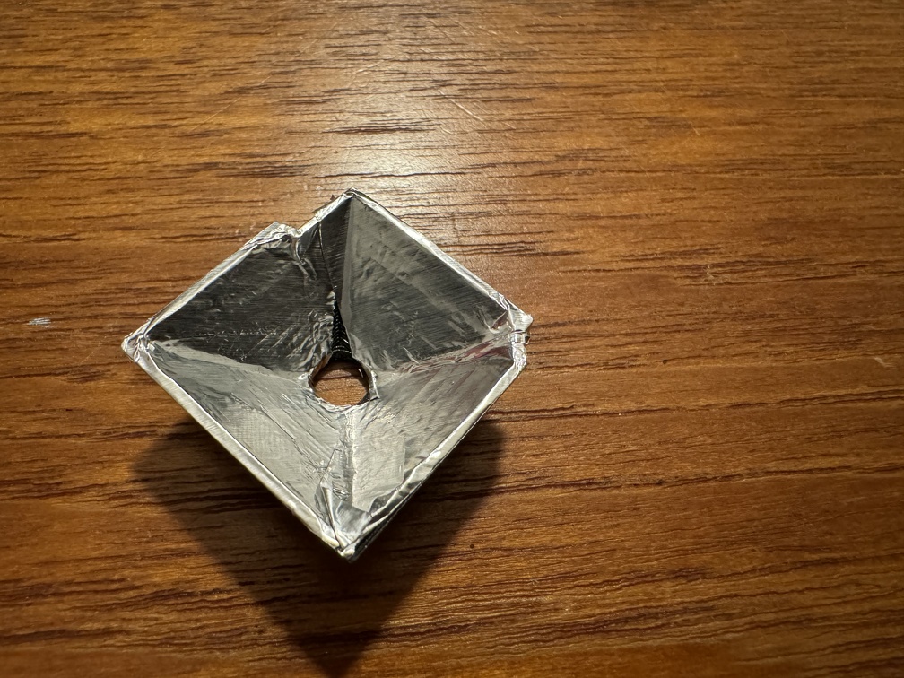
With the vent holes open, the stock LED inside is a little ugly looking, on the circuit board. Fortunately Dustin Grau designed a little insert that should help. I 3D printed it, and just need to line with aluminum to make it reflective (aluminum tape, or perhaps spray adhesive and aluminum foil), and it should fit right inside nicely.
I have a new perspex barrel coming, along with metal trigger and banjos, from Ben of Kent.
I need to install a real switch on the front ear of this 84 wand, like I did with the Afterlife one. (I have red ones, like the black one I used on the other wand) I'll do that a little differently this time, and use actual heat shrink tubing to cover it all, so I can actually make that switch the functional one, instead of the stock hat light switch.
And at that point, it's time to put in real hat lights (which I picked up from GBFans) and get an LED into that.
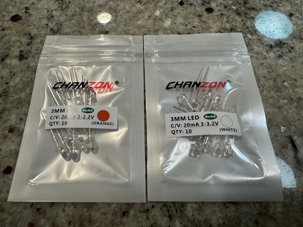
While I'm adding LEDs, the new black "hat light" on the main wand control box (UGH) needs to go, so I'll replace that, too. I know a cool mod using some new LEDs pulling off the slo blo LED (for the wand box) and the front Clippard area LED (for the front ear), so the two lights (four?) blink together in pairs. I have the new real hat lights in hand, along with the new LEDs:
So there's some fun mods still coming, for sure!
As a final thing, circling back to the pack for a minute. I usually have my pack displayed in the family room, but the time will come when I need to banish it to the garage, for a time, at least. Or travel a significant distance with it, involving more than tossing the bare back in the back seat.
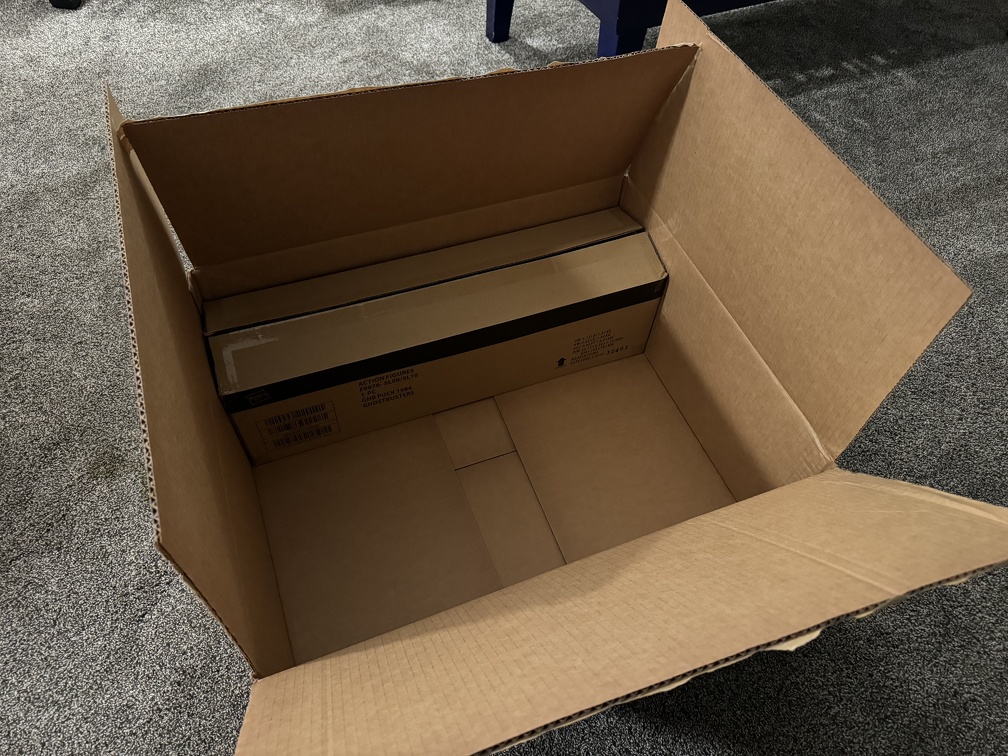
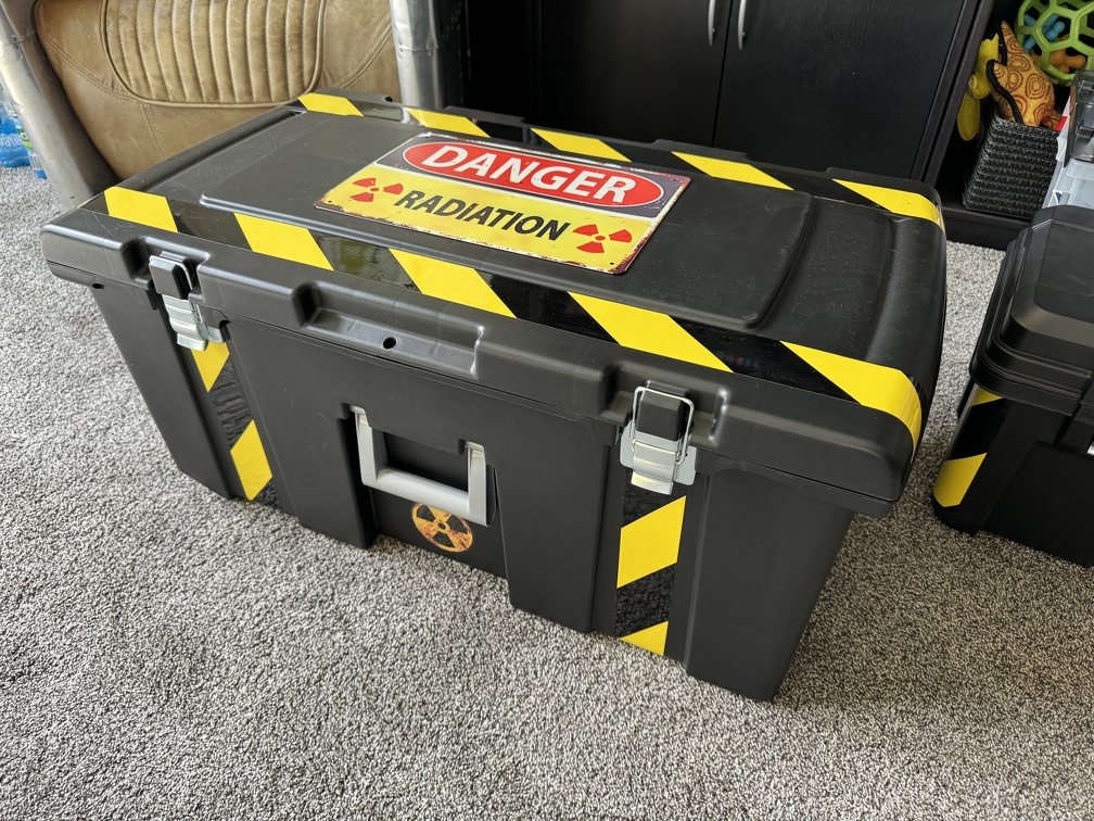
While I understand the Pelican 1695 case is *perfect* for proton packs, I don't have that kind of budget. I was tipped off about a cheap Sterlite Footlocker at Walmart that fits, and found it on sale for $27... umm, yes, please!
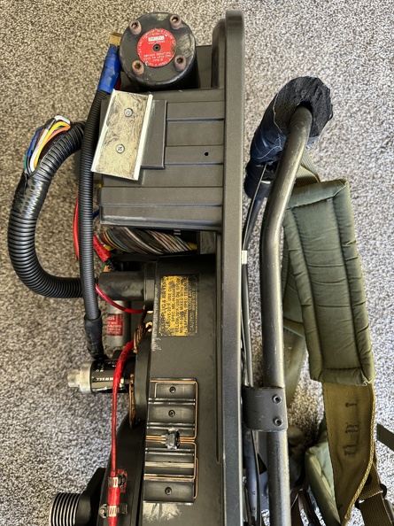
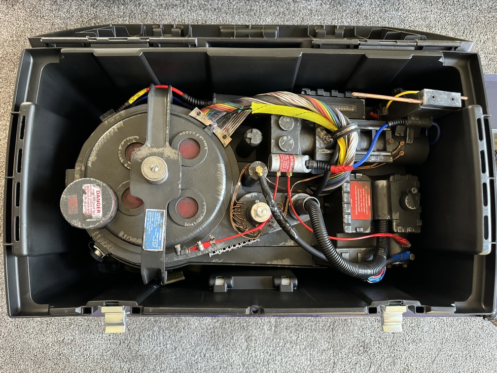
Unfortunately it's only *kind of* a perfect fit. The pack itself does fit inside:
... BUT with the Alice frame on it, it's an inch or two too tall to close the lid. (no, I'm not removing the Alice frame everytime I put it in the case)
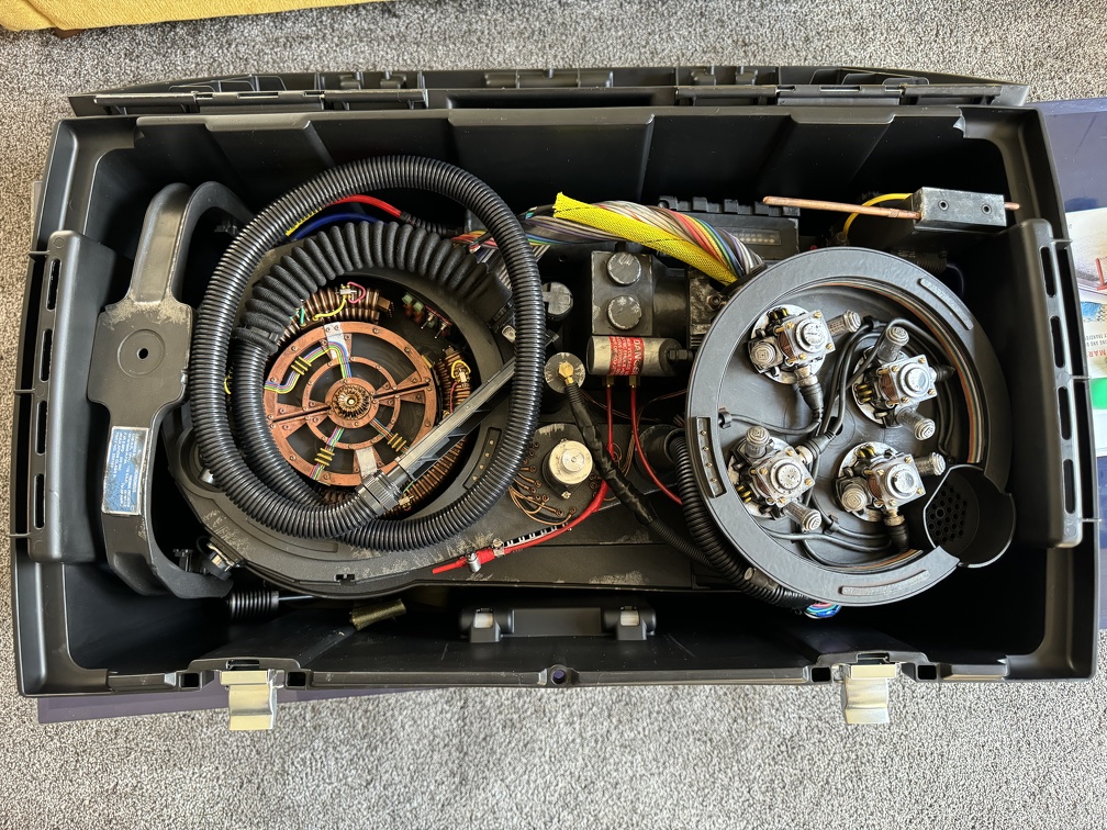
Fortunately, removing the bellows screw and bumper bar, and then flipping the cyclotron cover over DOES allow the case to close. The hose has to be detached, though.
Sharp eyes will notice that the wand is not inside. I haven't figured out if there's a way to squeeze that in, too, yet. Initial attempts have failed. BUT the wand is a lot smaller to deal with separately, if needed, so given the price, I'm reasonably satisfied for now. I just need to make the outside pretty, now...
We'll continue this, next time I return to this project. Hopefully this weekend, but we'll see.
I use that same case. I can get my pack hose and wand to fit in it however without flipping the cyclotron cover but do need to disconnect the hose and the bumper and bellows.
"Well that's fine Louis...we got arrested at night" *head slam*
Man, I thought I went deep last time, this time I went… deeper. Somehow feels like I got less done, too, but it WAS a fair amount. And important stuff. (IMO)
PACK MODS (Late Feb 2024)
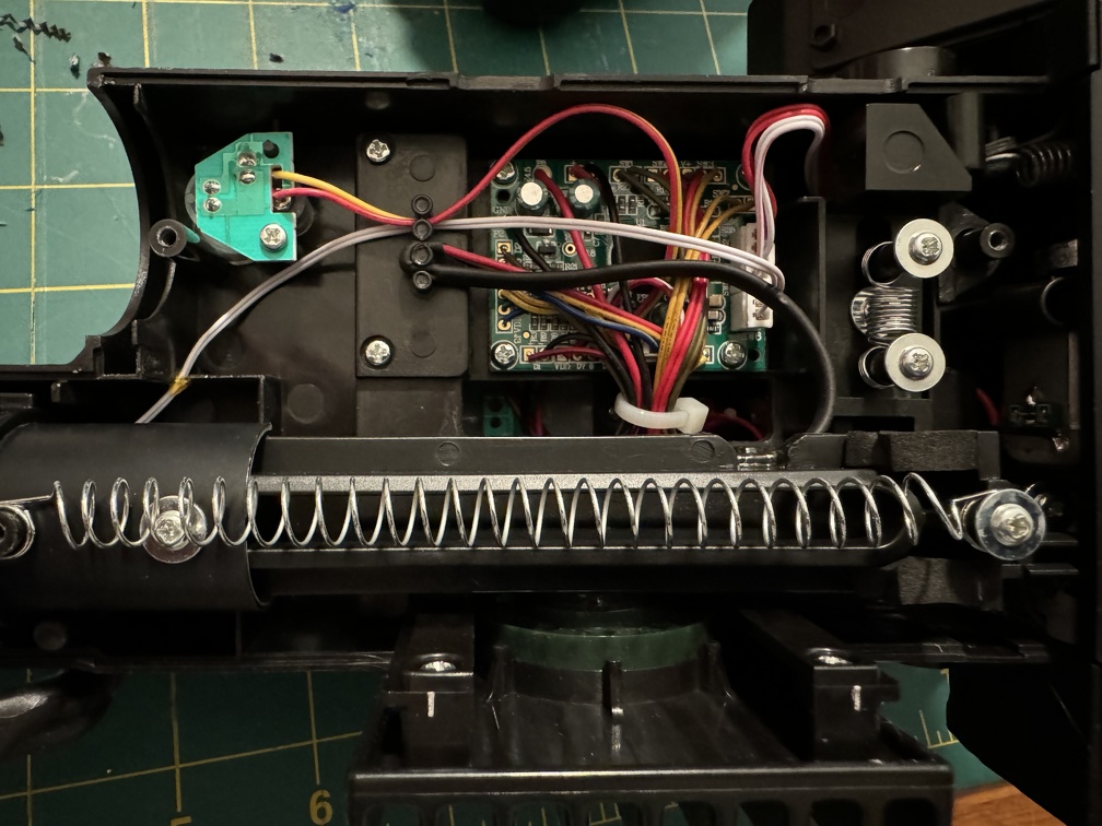
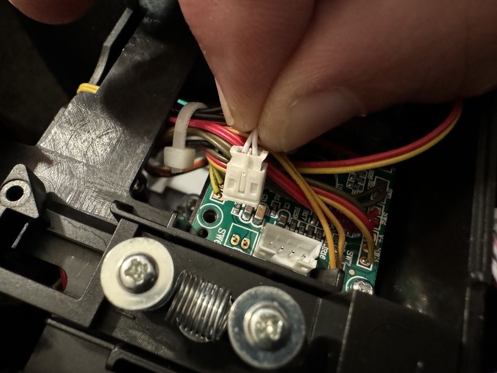
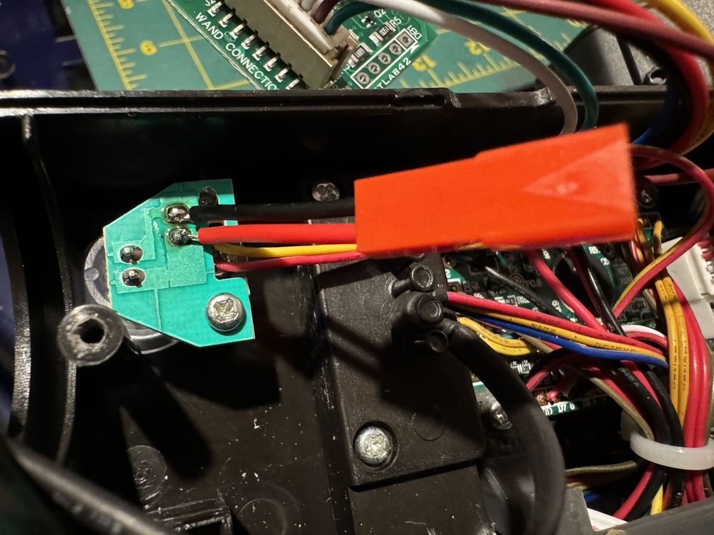
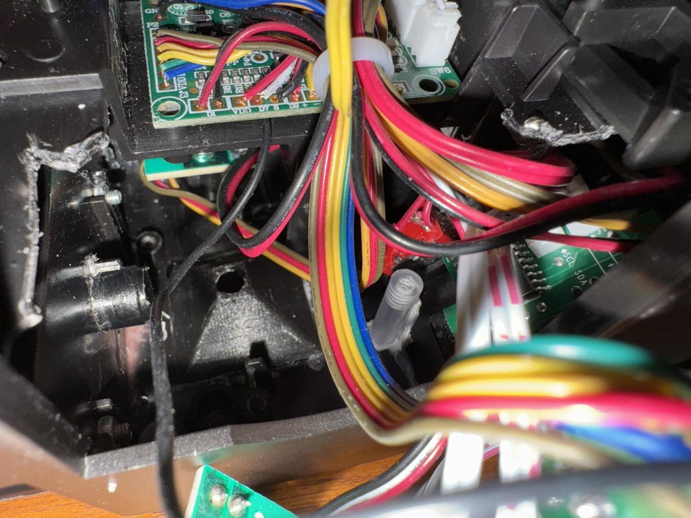
But first: I messed with my pack recently… I can’t recall why I felt I needed to, but I wanted to fix an issue since the NinaTunes upgrade I installed, which I hadn’t noticed at first. The internal cyclotron LEDs were white instead of red. Bizarre, right? This was pulling off the main board using Pierre Tien’s 4-wire wiring harness with the kit he sells, which intercepts the 4 wire motherboard connector. Somehow it screws up the color code and you get basically shite instead of red. By removing his harness, rewiring the light connector to stick with their original 3 wire setup, and plugging into the relay board NinjaTunes provides specifically for this, my lights are back to red.
That’s it for the actual modding, this round. BUT that led to some experimenting:
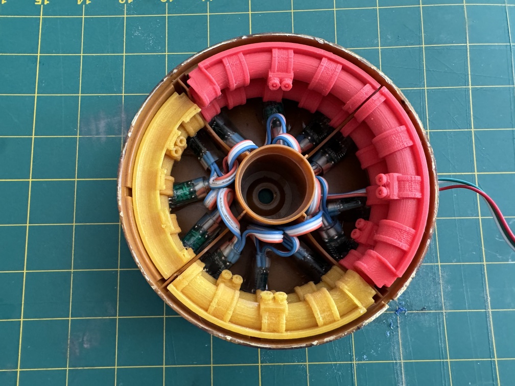
Thinking about making the interior cooler, with lighting, I bought the 3D model from Chris Hunt’s DragonWorkshop and printed some quick FDM tests with random filament I had laying around to test size (so pardon the multicolor mess, and the one incomplete print where it ran out mid-print… since I was just testing size I didn’t care). The good news is the main interior surround fits the stock cake just fine!
A friend is going to print these for me in resin, so they’ll be nice and smooth and detailed, and take paint nicely. So I just need lights that work, and fit.
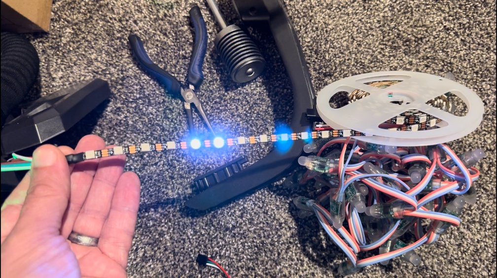
The bad news is the tubes for lights are a lot smaller than I expected AND the lights in my existing light kit are relatively huge… no way they’re going to fit. But fear not, I would have typed all this if that was where it ended.
A big issue is regular “standard” addressable LEDs use a tweaked ordering format for their color codes, and the instructions sent by the HasLab board AND the NinjaTunes board turn them green instead of the red of the originals. TacoBelli experimented a ton and found those one lights, WS-2811 Pixel LEDs, that happen to use the exact same sequence as HasLab (and NT, which copied theirs over, I guess?) that gives the proper red, instead of green like all the others.
A weird coincidence, however, is that Pierre Tran’s wiring harness for the HasLab board, which pulls 4 pin data from the stock HasLab board, and combines it into the signaling feeding the 3 wire LED strands, somehow screws it up, and turns the LEDs white instead of red (or green). But white is exactly what I want! So I am going to be able to use his wiring setup with non-standard LEDs and I should still have white light, instead of green. I can either stick with white, or perhaps get a red Gel and cut it into strips, and get red that way. Or some other similar hack, we’ll see.
The test works! (White!)
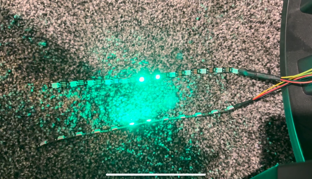
Another thing I learned is that these lights are dumb. They just listen for instructions, based on the order that they come in. Take their instructions, and pass it on, until there are no more. (This is why the HasLab board only supports 12 LEDs… they only supplied instructions for 12, so even if you have more, there are no instructions to pass on after #12.). BUT If you wire them in parallel… now there are TWO in the “light #1” position. Both light strands fire in sequence. This doesn’t scale well at all. BUT for a short 12 light sequence light this?
I rigged up a quick test with some extra-thin WS-2811 LED strip lights, and IT WORKS. (Jacked in without the extra harness here, so they’re green)
This will let me put lights in BOTH top and bottom tubes, and they’ll fire in sequence.
More to come on this mod. I need to work out spacing, and am I going to try to find LEDs that are spaced better or get STUPID and cut all 24 apart and solder 3 lines to each (both sides, so 6 per LED means around 150 points to solder, with the extra wiring, yikes) to extend them to an exact custom distance. Research continues…
I believe my Redman motherboard is supposed to come soon (PLEASE???) so I’ll get back into all that when that arrives, and I’ll get into the pack again. And I’ll relocate switches, clean up the snack compartment, etc.
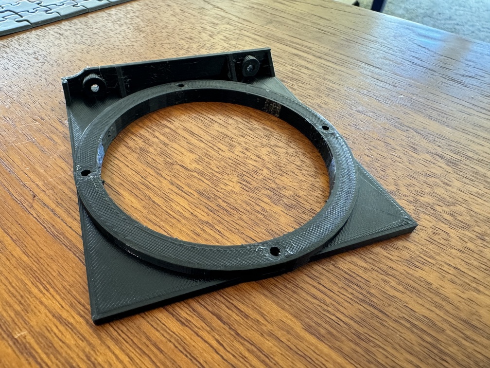
Oh, and one small mod, I’ve ordered a 3” speaker for my pack, and printed a speaker mount I found online:
… so that’ll be a quick easy swap, and give my rumble a little more bass.
I ordered the Dayton 3” speaker, but an aluminum cone one which apparently weight considerably less than their regular 3” one. All these mods are starting to add up, in weight! Especially with the motherboard about to add a couple more pounds, too.
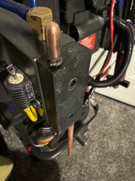
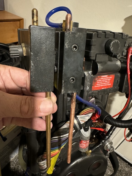
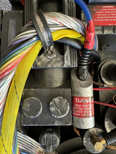
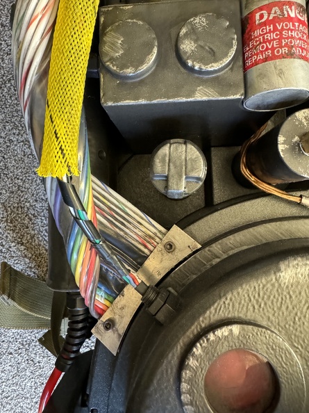
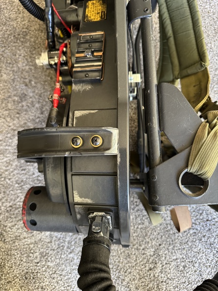
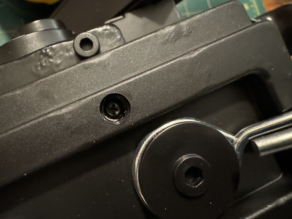
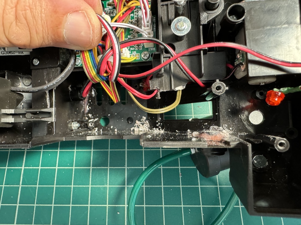
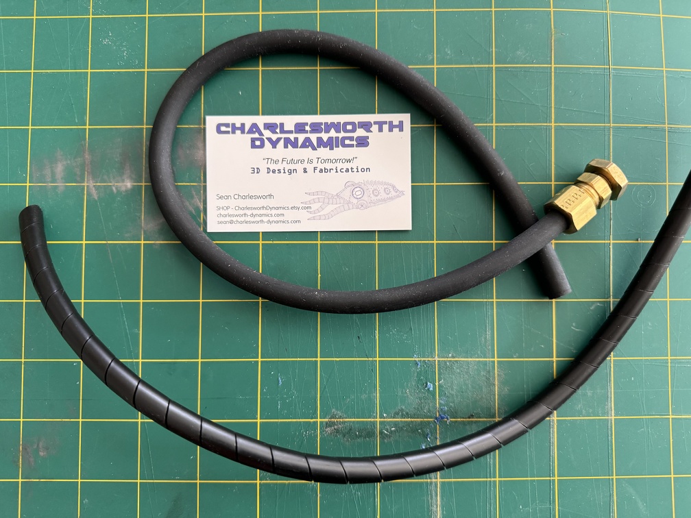
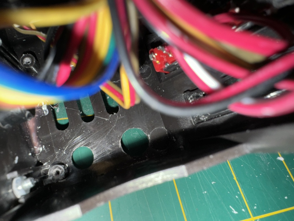
Also: At one point I realized I had missed one brass connector on my pack… the one that hides behind the ribbon cable, with the plain black tube coming from that same hole to inside the pack. That cannot stand, so I bought the real brass (from Charlesworth Dynamics). That’s on the slate for next time, too.
Aaaand, as you can see in the photo above, I somehow missed that the wire-wrap around the wires coming from the flex tube was NOT the screen-accurate reverse wrap stuff, so I’ll take care of that, too. Charlesworth had the good stuff here, too.
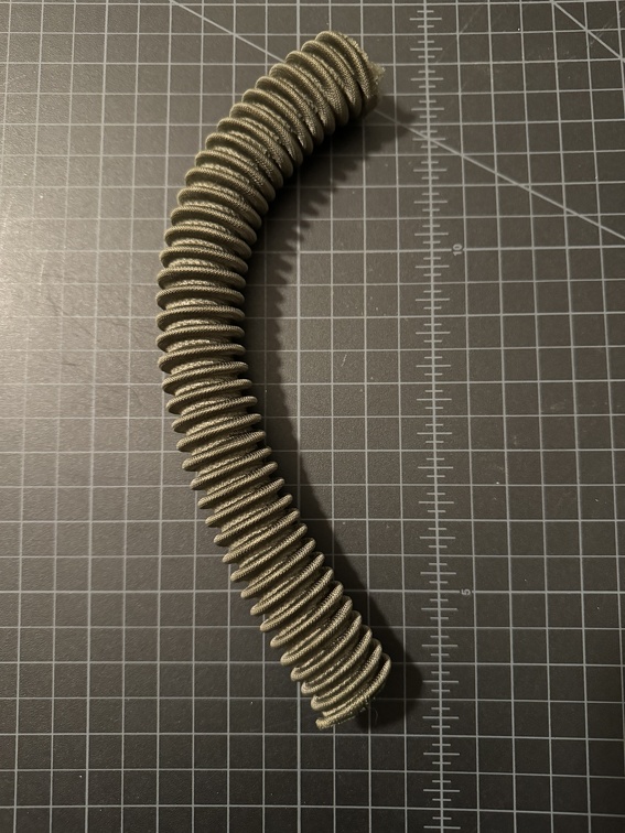
And finally, I managed to score an aged section of the real rebreather hose, naturally faded to the accurate aged green instead of the dark green you see some using. At some point I’ll swap out the black hose on my back now, for this stuff.
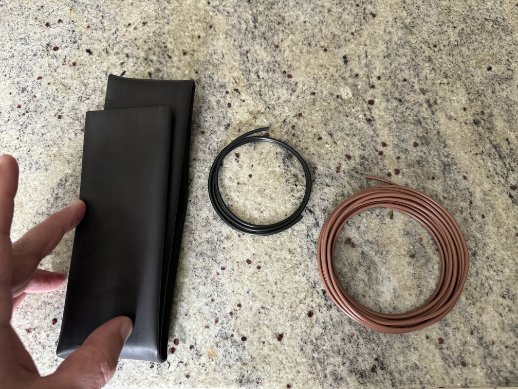
And last but not least, I got the wire I’ll need to finally replace the wire shroud surrounding the Clippard valve. So that mod is in my future.
Also pictured, above, is 1.5” heat shrink tubing, for my wand ear mods. Which finishes out the future pack stuff and brings us to:
WAND MODS (March 2024)
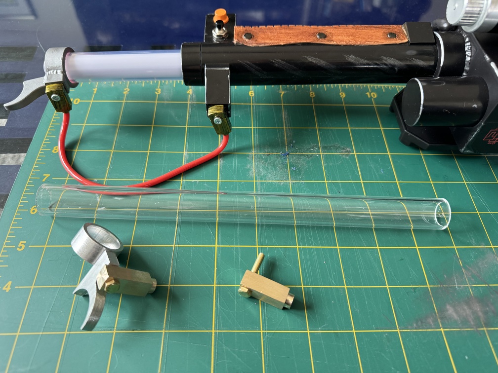
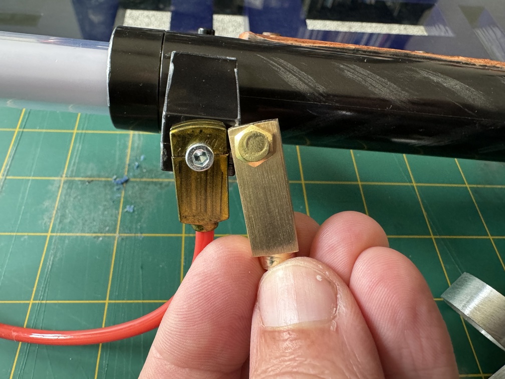
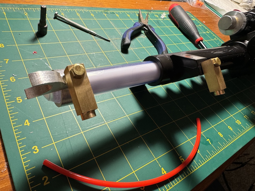
My Ben of Kent metal trigger ring and brass banjos finally arrived from overseas, yay! (Un-modded Spengler wand used for reference, as it was on hand, but I’ll be using all this to mod my 84 wand instead)
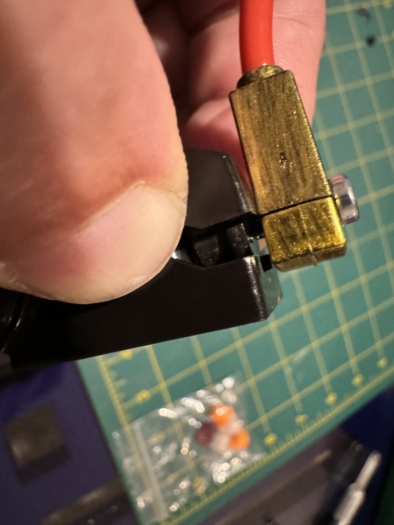
The real metal brass banjos are huge improvement over the stock stuff. Bigger, too.
And the metal trigger ring is super sweet, too:
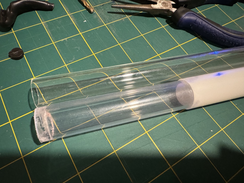
Ben threw in a Perspex tube as well, which turns out to be *identical* to the Haslab one. I had planned to install it, but once I got in there, I decided to instead just save this, in case I need it in the future. Not really any different from the original, so why change it?
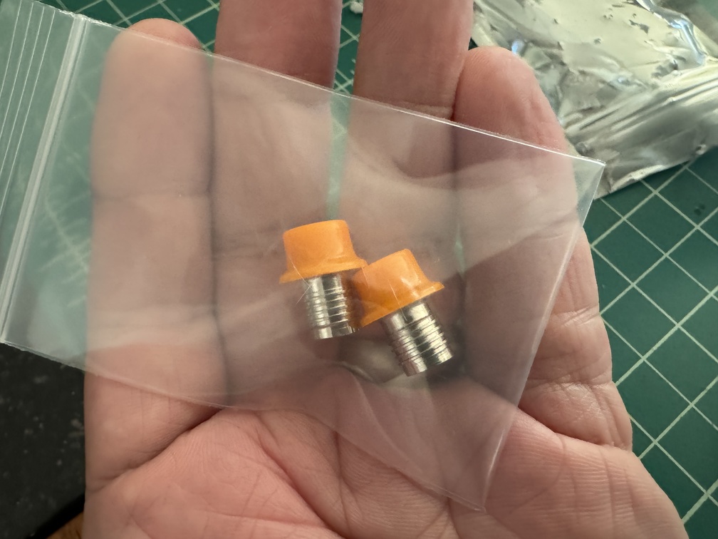
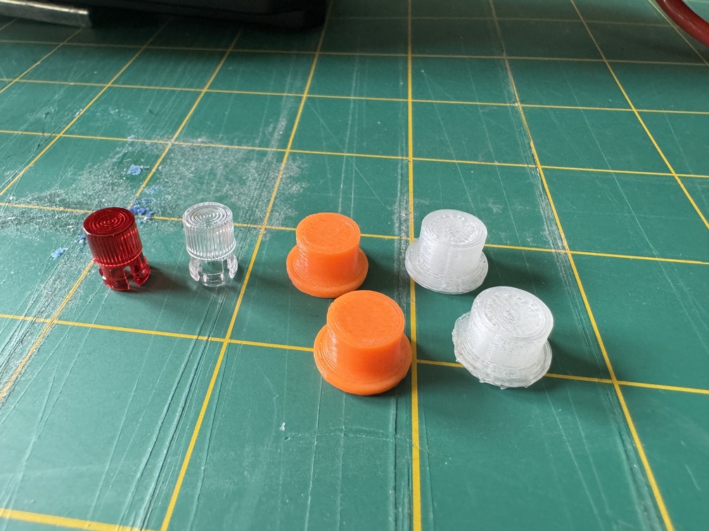
I also bought a little kit of resin hat lights and it turns out they came with fresnel lens replacements for the wand box and slo-bio LEDs as well, which I had not realized. Except it turns out they’re not the exact match for the originals, and the exact ones are actually available, so I’ll hold off on installing those.
Step one for the wand mods: INTENSE wand breakdown.
Opened ‘er back up again. This is how it was at the start of this round:
More Hasbro screw plugs got yanked. I pulled the ones out the barrel grip, too.
Disassembled the whole barrel:
… mostly because a main target here is the fake switch nub and hat “light” in the ear at the end, and I wanted to do it without hacking the back of it to hell, even though I’ll be covering it all over with the heat shrink tubing, eventually. That’s a ways off, though, so I needed to be able to close it up normally for now. Screw plugs it is.
Note removing the front handle assembly means cutting off the fake wires between the box and the handle. They cut off easily… I don’t see a way to do this without actually destroying that piece. (Which can be faked again with some actual tape-wrapped wire, stuck back in the same holes, if I want)
I was NOT able to completely split apart the handle, annoyingly. I think it may be glued around the ring at the base? I didn’t want to rick breaking it so I was careful not to open it more than this:
That gave me enough to work with, fortunately. It all needed to be opened like this, because these have to go:
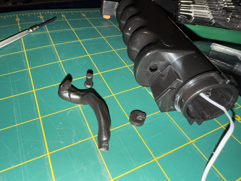
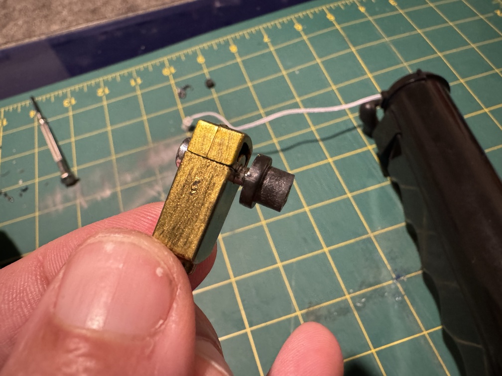
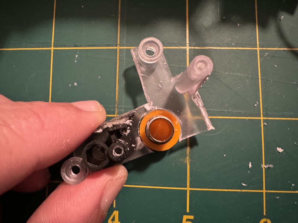
I needed to remove the ears and fake banjos and tips anyway. The front tip trigger piece came off as easily as my past one did (just heat it with a hairdryer and literally peel the dang thing off), but the second banjo will NOT budge. But once the plugs were out and the screws unscrewed, the two halves of the handle could be pushed apart, and you can see why:
There’s a black round thingie attached in there, that just spins!
Once you open the handle enough to remove it, you can see why it was so hard to get out. That piece does NOT unscrew, btw… it’s set in there somehow, and twisting it forcefully just spins it around more.
Fortunately, it’s not actually needed to come off further than it already did, since I’m replacing it with metal.
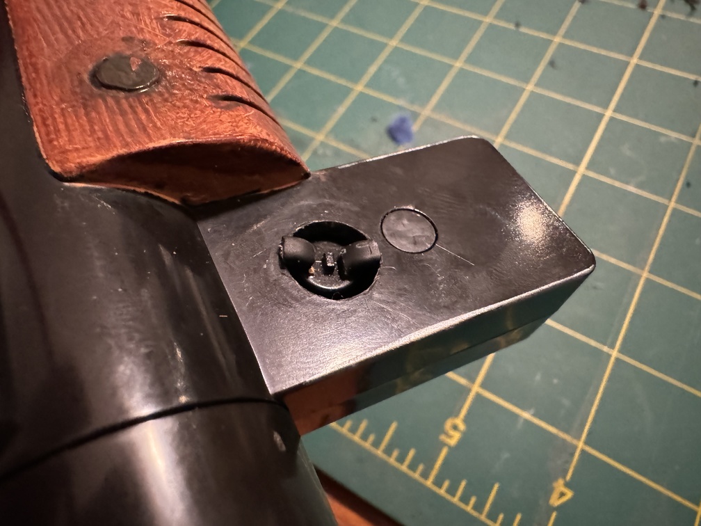
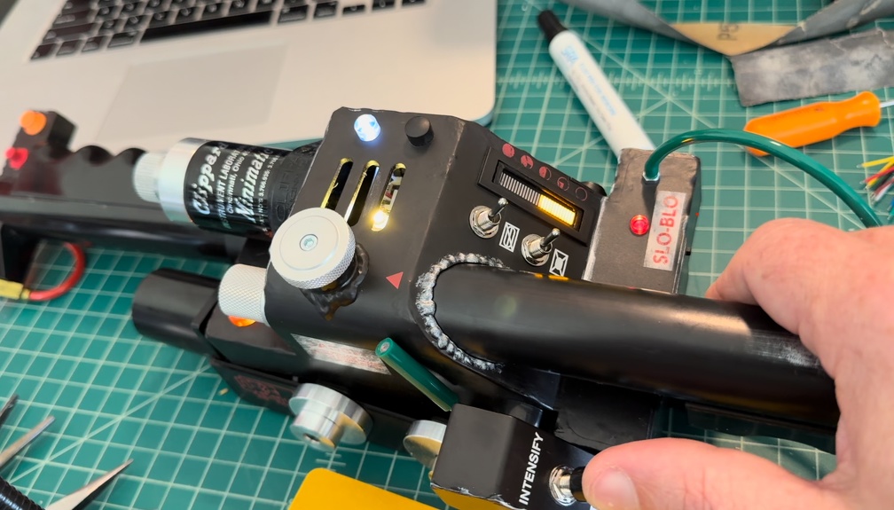
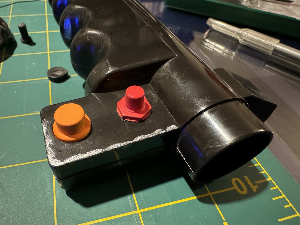
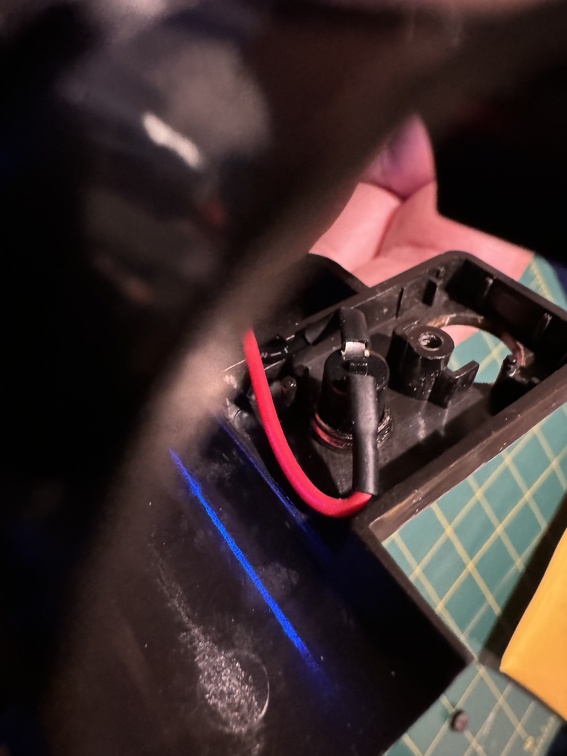
On the other side of the ear, opening it like this lets you pull out the orange hat top, the PCB-mounted switch, and access where you need to drill to install the REAL switch:
Onto the mods, one thing I wanted to do was put an actual light under the top hat light, and make it a LIGHT, and not a switch. The fake switch would then be a… real switch. (Red capped, unlike the Spengler wand I previously modded)
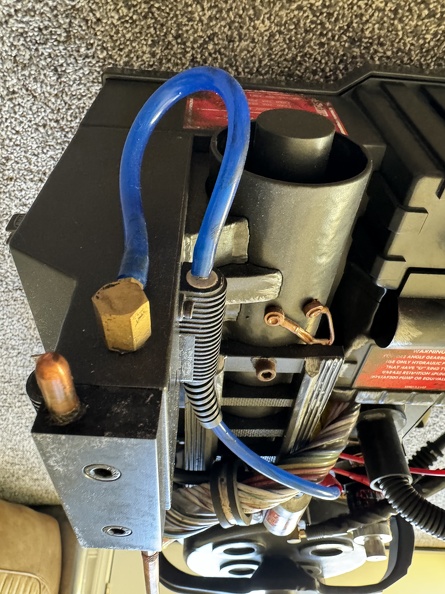
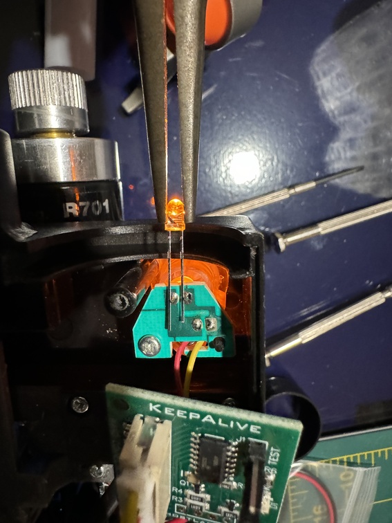
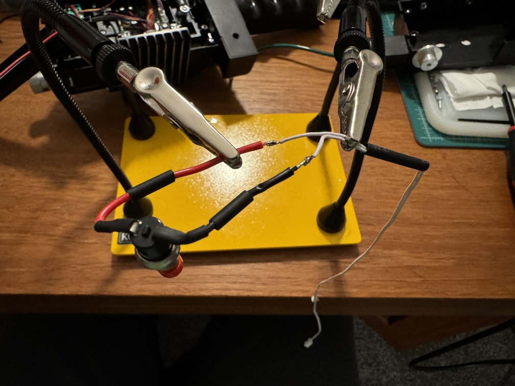
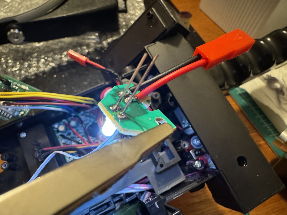
Recommended to me was pulling power off the “Step LED”, on the flat part below the Clippard valve. I tested my orange LED against the board contacts, and sure enough it lights. Woohoo!
Time passed, and I piggybacked wires off that circuitboard and ran them up the ear. Fun thing I learned about LEDs, naturally after I closed things mostly up: “Forward starting voltage” is a thing, and if the LED specs aren’t exactly in alignment, especially if one has a longer wiring run than the other, they won’t both light. One turns on, the other turns off. Took me a while to work out the issue. Ultimately I solved it by replacing the orange LED in that step / Clipped location (turns out that’s a Hasbro mistake and that one should be milky white anyway!) with a white LED, and a second identical white LED up in the front. The front one goes into the orange hat light anyway, so it didn’t NEED to be orange. And now both work. But wow that was a lot of work to figure out and solve…
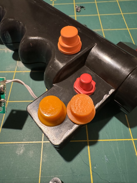
Back to the modding, here you can see three orange hats: The upper one is the fake Hasbro one that is NOT a light, but just pushes that button. To the right is the 3D printed one from Ben of Kent. It actually matches the REAL hat light (left-most) from GBFans quite well. But since I had the real one, of course that’s what I’m using.
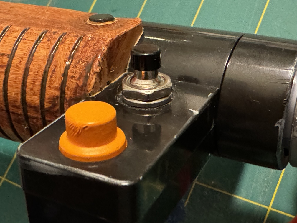
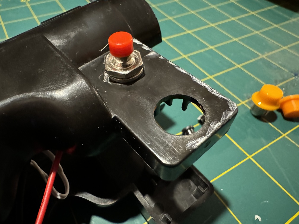
The SPST pushbutton switch went on as easily as you could hope, just like last time.
The only complication of, well, now I needed to actually solder on the wires cut from the stock switch PCB. Not a lot of room to work in there, and recall you can only open the two halves so far, but still not all that bad. Contacts have to be bent so they’re not deeper than the space.
Next, the hat light dropped in nicely… sort of. It’s smaller than the stock hole, but two drops of superglue and some hot glue later, and it was ready for an LED:
Because disconnects are good, I added a JST connector to the little LED circuitboard:
Test lighting is a success!
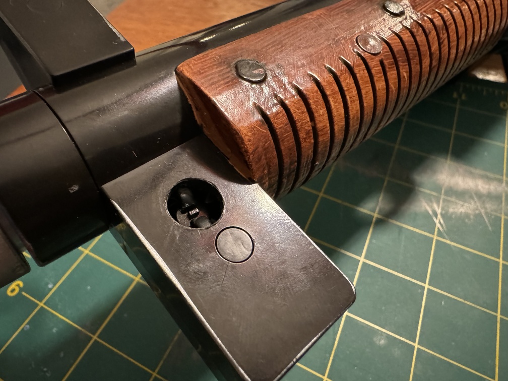
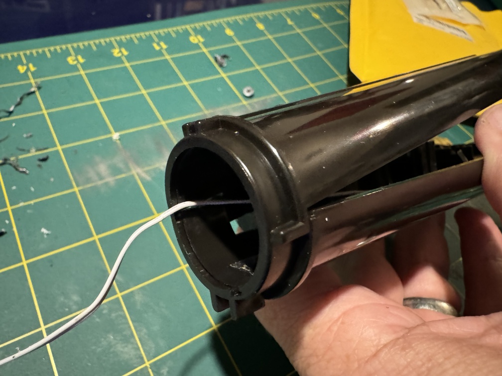
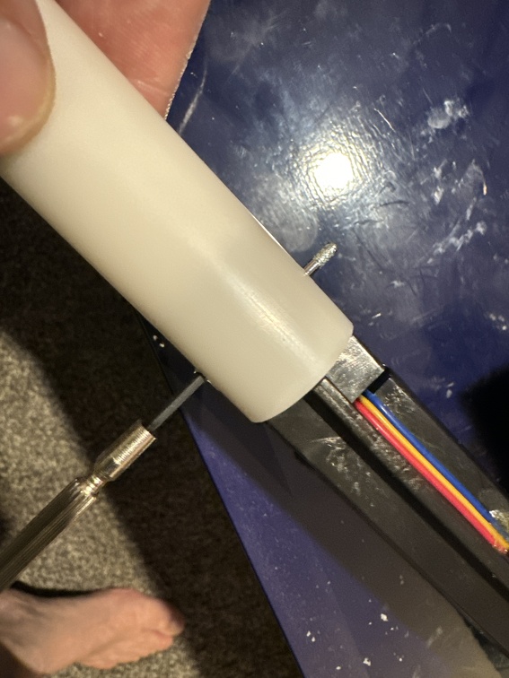
But first, because I thought was going to be doing a full barrel swap for the BoK clear tube, I took that entirely down. Located and removed the pin that’s hidden entirely under the white plastic tube (have to look for the tiny white spot UNDER the plastic, in about this position, and go fishing with your drill, opening both sides to get it out!)
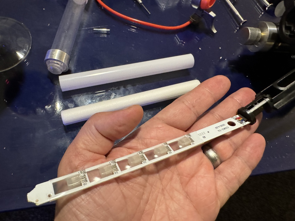
Then everything just slides off until you’re at the bare LEDs.
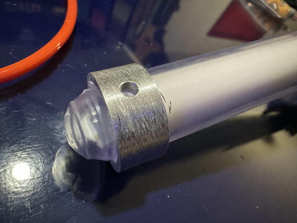
I know some have a preference for the bare LEDs, but looking at then, I was not convinced, and decided I like the white diffusion layer look over them better,
And realizing the BoK tube really is identical, I didn’t see a point to trying to tear off the white sleeve to actually swap them.
I confirmed the BoK trigger ring fits the stock tube perfectly as well. Very nice!
This is the point at which I put things back together, in front, and ran into the road block when I realized that BOTH LEDs were NOT lighting as planned. Troubleshooting ensued, and eventually, I had to swap the stock orange LED in the wand body with a white one (especially since I realized it was supposed to be white anyway!):
AND re-open the front ears, pull out the LED I had just carefully glued in place (*sob*), swap THAT LED for white (but inside the orange plastic hat, it’s still orange), and THEN close up the front. Wheeee!
Moving onto the top hat light (main wand body).
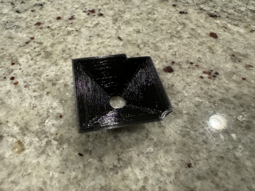
Buuuuut first, I wanted to check out the vent light reflector that I 3D printed.
… Meh?
I coated it with foil:
… and installed it:
… and HATED it:
(Even through it won’t be exactly like this once it better held in place)
BUT I experimented with some flashlight reflectors, and wow, getting the height exactly right to match the stock LED, which is on a twin LED PCB. The space in there is AWKWARD to say the least.
Ultimately I punted, removed the foil reflector material, and just installed it black. It’s… better. Better than looking through the vet holes onto the bare PCB and mess inside. Not great, but better. So it stays for now. I stuck it in with a couple dabs of hot glue, awkwardly dribbled down from above (so hard to get a glue gun inside that cramped space!). I can tear it out later if I get annoyed enough.
Onto the hat light install.
I started by installing the orange hat itself, uncertain if I was going to bother with adding the LED right away. (The struggle with the mismatched LEDs in the front ear took a long time to resolve and took a lot our of me.). I watched an install video by Jono, of gpstar fame, on YouTube. His installed stated that if you still had the clear plastic from the bargraph LED install, you were going to need a spacer to keep the top hat from sticking out too far. I actually kept a potion of the plastic, for structural reasons, so this applied to me.. You can see the L shape, in the “installed it” photo, two up, bending around the “reflector” piece.
I first drilled the top hole, which is smaller. (And required buying a 25/64 drill bit, since I didn’t have one before and wanted that perfect hole on top)
But with the plastic piece in there, it fit really poorly, and didn’t come up nearly enough.
I wonder if the Spengler want and the 84 wand have significantly thicker top panels? Because ultimately, I had to drill a hole in the bracket entirely, so the orange hat was flush against the black plastic top.
Then it fit pretty perfectly.
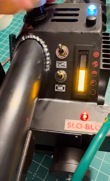
After that, it was a matter of stealing power from the line feeding the Slo-Bio LED. I used an orange LED, hoping it would match the red Slo-Bio LED’s electrical characteristics better, and thank GOD, it did. No issues with this one, unlike the front ear LED. Maybe because it’s a shortly wiring run? Not sure, but I’ll take it.
THEY ALL LIGHT!!!
At this point, I closed the inside back up. *immense sigh of relief*
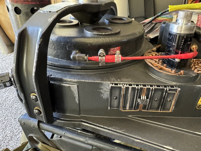
OH! I left out one thing. At some point in all this, I managed to accidentally tear off the speaker. WHOOPS! So I added a JST disconnect inline, so next time I’m working inside, I can just remove the damn thing instead of it flopping and dragging all other place while I work. Not pictured.
AND NOW THE TIP:
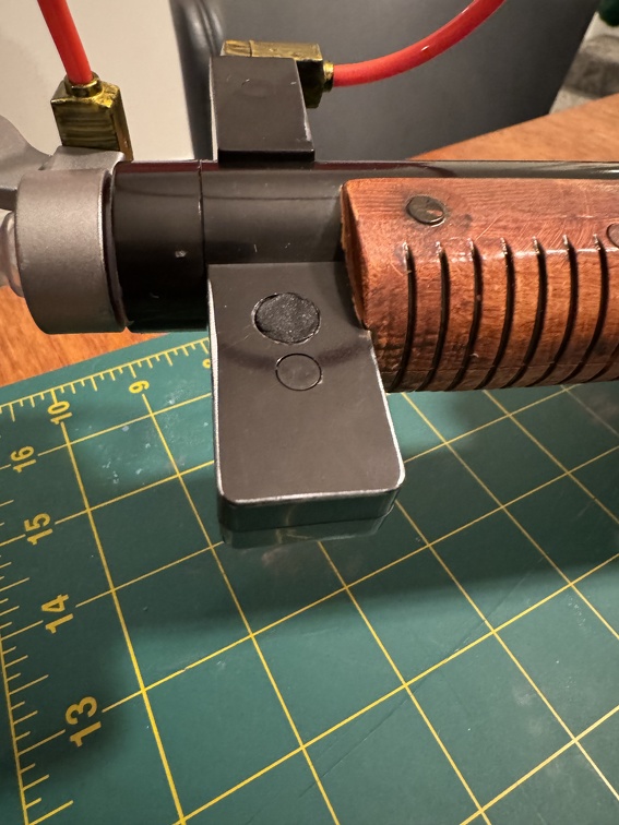
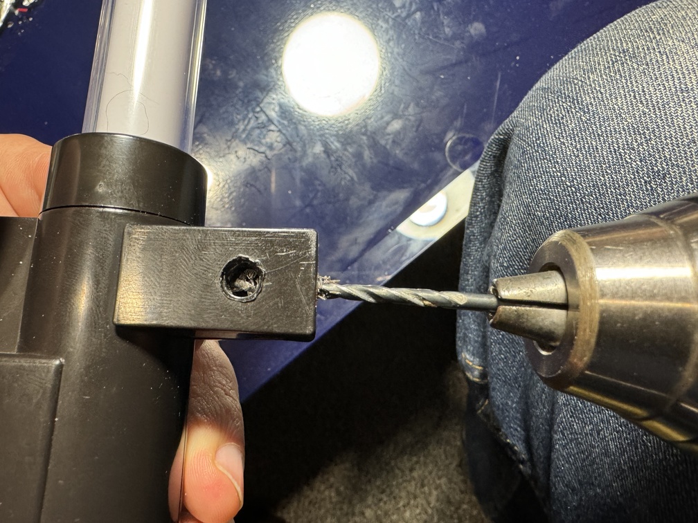
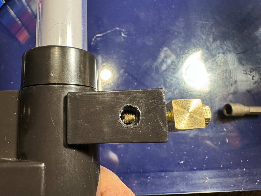
First installing the banjo onto the ear, drilling into the middle, where the original hole also was. The BoK banjo screw is pretty beefy, so a little drilling is good, so the screw doesn’t force the two halves open. Naturally, the path goes RIGHT into the screw post. So I guess this side won’t have a screw. I can glue it later, and/or fill it with milliput or something, if I feel it needs it. For now, drilling STRAIGHT in, right into where the head of the screw would have been:
The screw crossed that screw hole opening and goes slightly into the other side:
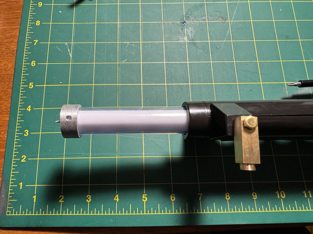
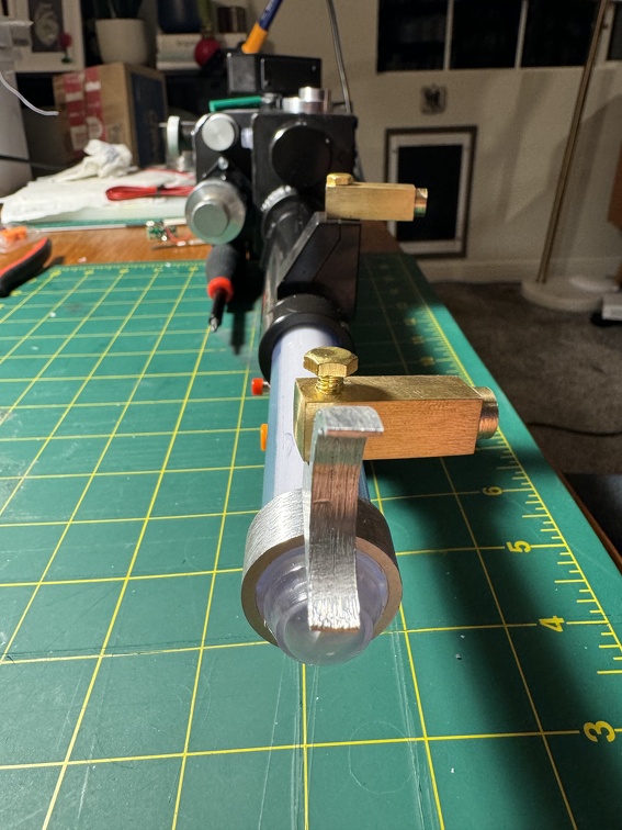
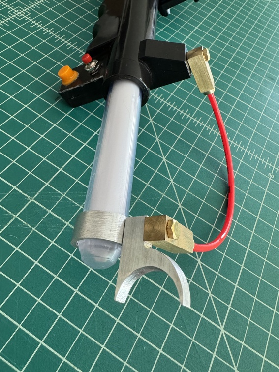
One down! Very nice! I slipped the ring over the tip to decide where to locate the front trigger assembly:
Once I was happy with how it all lined up:
… it’s time to drill, baby, drill! I included the OEM clear tip under the lip of the ring. I figure this way if I decide to extend the clear tube with a short extension (GB1 style), there’s a little material under the lip where I can glue everything together without being seen. Meanwhile, the set screw goes into the main part of the tube, as it should.
It’s best to be cautious, drilling into relatively fragile material that likes to crack under strain. So for the set screw hole, I started with 1/16th bit, moved up to 7/64, that was still a touch tight, so up to 1/8”. Finally, even that seemed a hair tight so I used the a tap to thread the hole, matching the screw itself. Again, you really don’t want to put too much pressure on the hole, especially in thin brittle material.
I’m happy with how it turned out, though!
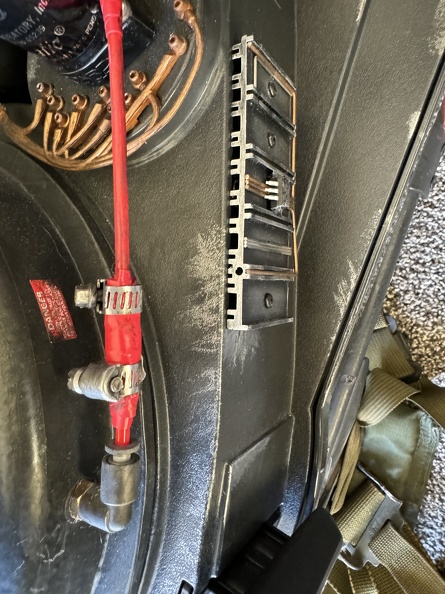
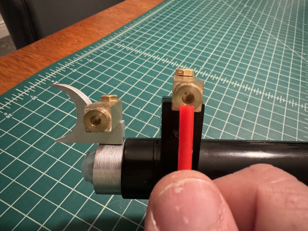
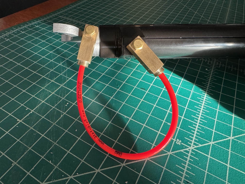
Last step for this is to get the red tubing into the bottom of the banjo. The red tubing I bought from GBFans was a little large for the holes…
So that’s a tomorrow problem.
LAST MOD OF THE DAY (night?)
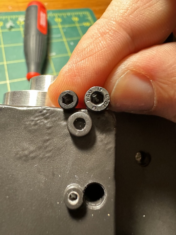
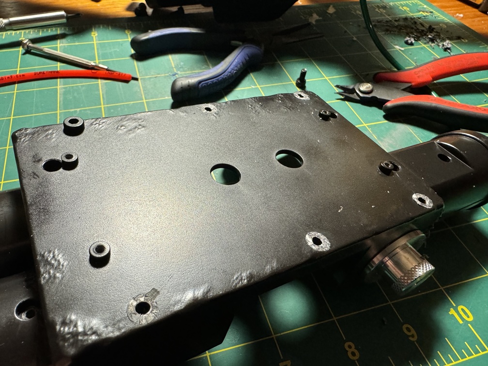
Real screws are better than molded plastic pretend screws. So I measured M3 and M4 hex nut screws against the molded ones on the bottom of the wand lining both sides of the rail, and decided M4 is the right size.
So 6 quick drill holes later, and some quick work with my flush cut nippers, I screwed in those M4x8 screws, and that was that.
It’s a little detail, but it makes me happy.
Truly done for the day:
And then it was ...tomorrow? I had messaged BoK before crashing, and when I awoke, Ben had already responded, just saying to drill it slightly bigger. Brass is soft, so go slow and it was very easy.
I need to check some refs to see if writing is on the screen used red tubing. If not, it should come right off with either isopropyl alcohol or perhaps some quick acetone. Or just flip it around to the other side so you don’t see it LOL
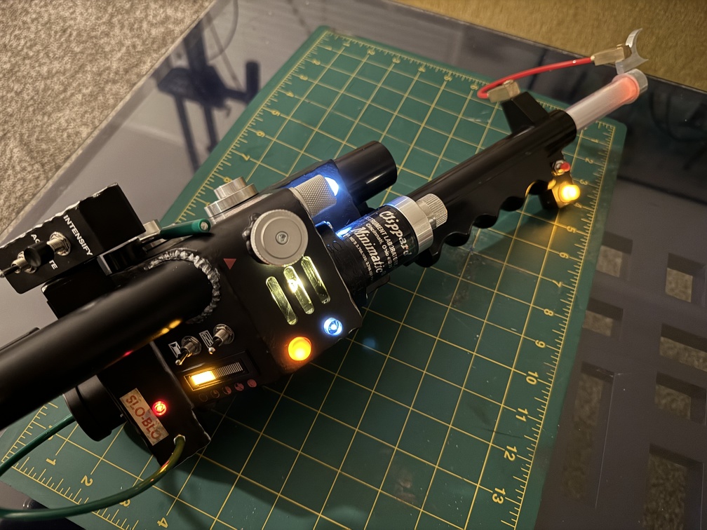
Here she is all lit up.
~~~~~~~~~~~~~~
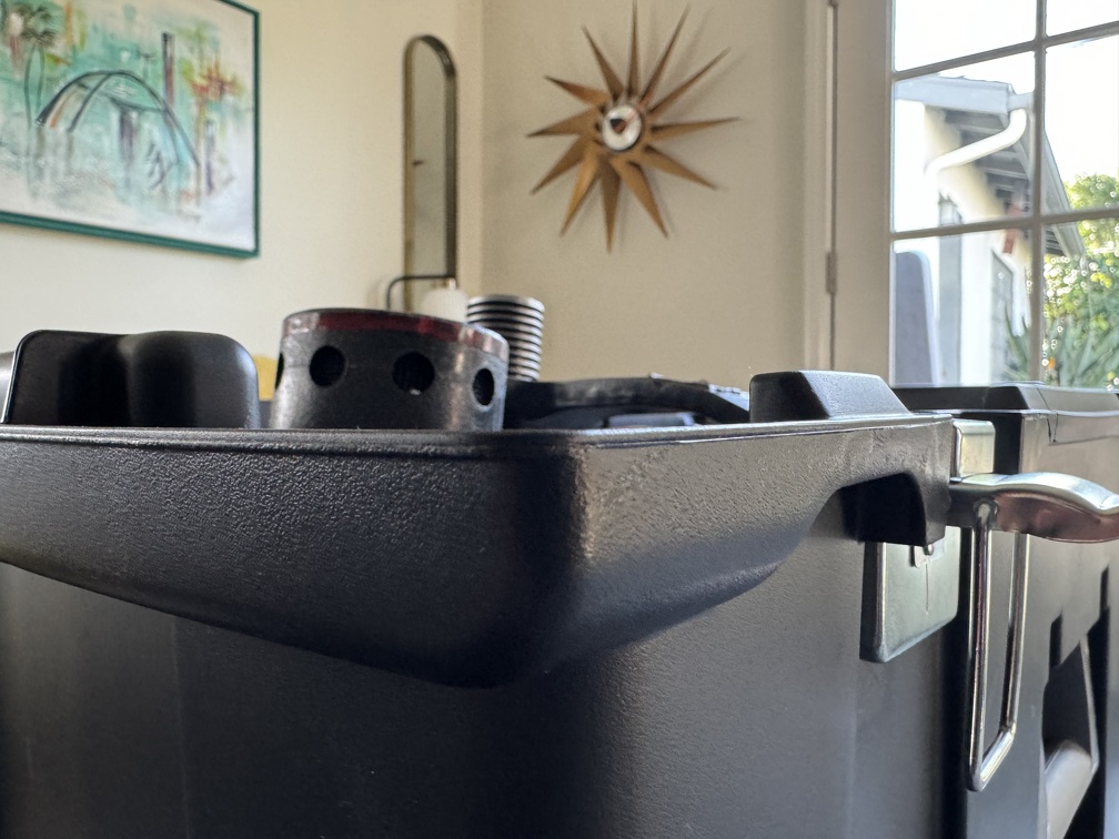
Final note: I tarted up my pack storage trunk a little. Not done yet, but I’m enjoying it so far. (Decor ideas mostly borrowed from the guy on Facebook who recommended the trunk)
Until next time…
(PS please pardon any typos or pure incoherence ... that was a LOT of writing, it's late, and I'm wiped. Maybe I'll do an editing pass some other time. Meanwhile you get my rough draft LOL)


 - By mrmichaelt
 - By zeta otaku
 - By Indy Magnoli
 - By Gatchigirl