A couple of people have asked me about how the NeoPixels in my mod should be wired up, so here is a little explainer...
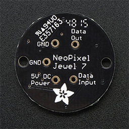
Firstly, I used 3x Adafruit NeoPixel Jewels - these feature separate white LEDs in addition to the RGB and are available in different versions which have different white temperatures. I went for the 'Cool White ~6000K' version as this provides the brightest light - perfect for not looking into the trap

Each Jewel is clearly labelled on the back so you can see where each connection is made:
Luckily, NeoPixels can be chained together, so the wiring is nice and simple. Here's a diagram of what I did:
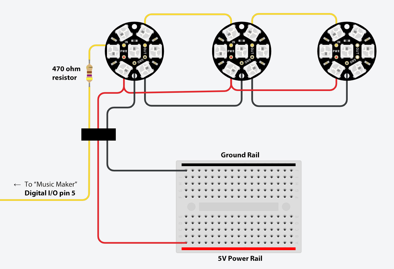
Take a longer
yellow wire and solder one end of the wire to the end of a 470ohm resistor (these have the colour bands: Yellow, Violet, Brown, Gold). It doesn't matter which end of the resistor you solder as they work in either direction. Then cut a small section of
yellow wire and solder it to the other end of the resistor. I recommend covering the resistor and the soldered points with heat shrink tubing at this point. Now solder the loose end of the short
yellow wire to the "Data Input" pin on the first Jewel. Feed the wire into the pin from the bottom of the Jewel and solder on the top.
Now cut two more
yellow wires, each about 4" or so. Don't make them too short otherwise there wont be enough slack for them to wrap over the speakers inside the trap. I made this mistake originally. With one of these wires, connect the "Data Out" pin on the first Jewel, to the "Data Input" pin on the second Jewel. Repeat this with the second wire - "Data Out" on the second Jewel to the "Data Input" on the third Jewel.
With the
red power wires, you need three sections together as the Jewels only have one power pin each. Make one long
red wire and two shorter 4" wires and twist the bare ends as shown in the diagram. Solder the combined wires to the "5V DC Power" pins on each Jewel.
Similar story with the
black ground wires, except you don't need to splice them together. Connect one end of the longer
black wire to one of the "GND" pins on the first Jewel. Then solder one end of a 4"
black wire to the other "GND" pin - connect this to one of the "GND" pins on the second Jewel. Repeat this to connect the third Jewel.
You should now have them wired up as you can see in the diagram. This leaves you with the three long wires connected to the first Jewel. The
red is connected to the power rail on the repurposed breadboard (this is detailed in Sean's guide) and the
black is connected to the ground rail on the breadboard.
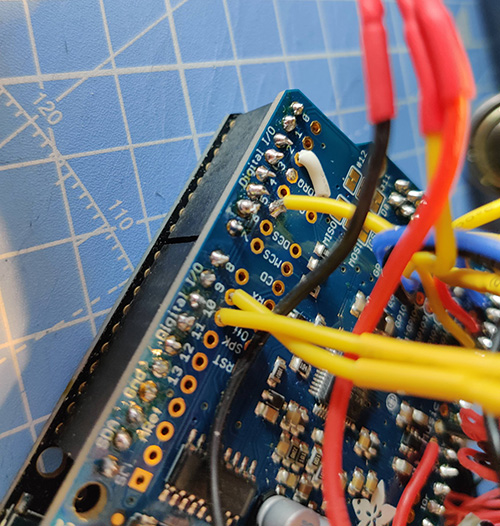
The
yellow wire needs to be connected directly to the Music Maker shield. This is where I had to deviate from the guide a bit. I had success by connecting the
yellow wire from the Jewels to Digital I/O pin #5. I think Sean has one of the servos on pin #5, so this needs to be moved. I had success by moving the servos to pins #9 and #10:
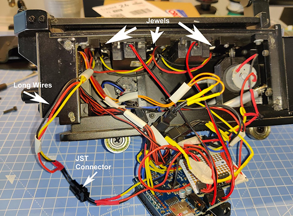
And here's it is inside the trap with the rest of the rat's nest using my modified LED holders. Rather than solder the three wires directly, I've cut the long wires and put a 3-pin JST connector in the middle so I can disconnect it at any time. Sean uses this technique for everything else, so you should have a spare connector that would have been used for the LEDs he originally intended.
And that's it! You just need to upload my code (provided on page 1) to the trap, making sure you have the additional Arduino libraries installed and have the more accurate SFX files I've provided on your SD card.
Hope that helps

Dave


 - By mrmichaelt